Other Parts Discussed in Thread: ALP
Hi Ti supporter,
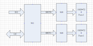
1 . 941-> 2 Des 948 -> 2 1920*720 panel, as folllow
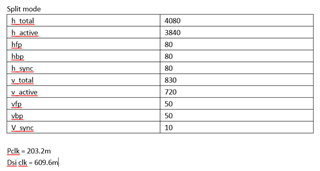
2 . panel spec.
3 . reg config
(ti941_addr, 0x01,0x08); //Disable DSI
(ti941_addr,0x1E,0x01); //Select FPD-Link III Port 0
(ti941_addr,0x03,0x9A); //Enable I2C_PASSTHROUGH, FPD-Link III Port 0
(ti941_addr,0x17,0x9E);

(ti941_addr,0x06,0x59);
(ti941_addr,0x07,0x30);
(ti941_addr,0x08,0x32);

(ti941_addr,0x0E,0x03);
(ti941_addr,0x0F,0x03);
(ti941_addr,0x4F,0x8C); //Set DSI_CONTINUOUS_CLOCK, 4 lanes, DSI Port 0
(ti941_addr,0x5B,0x07); //Force Splitter mode
(ti941_addr,0x56,0x80); //Enable Left/Right 3D processing to allow superframe splitting

(ti941_addr,0x1E,0x02); //Select FPD-Link III Port 1
(ti941_addr,0x03,0x9A); //Enable I2C_PASSTHROUGH, FPD-Link III Port 1
(ti941_addr,0x17,0x9E);

(ti941_addr,0x06,0x61);
(ti941_addr,0x07,0x30);
(ti941_addr,0x08,0x34);

(ti941_addr,0x0E,0x03);
(ti941_addr,0x0F,0x03);
(ti941_addr,0x4F,0x8C); //Set DSI_CONTINUOUS_CLOCK, 4 lanes, DSI Port 1
(ti941_addr,0x5B,0x07); //Force Splitter mode
(ti941_addr,0x56,0x80); //Enable Left/Right 3D processing to allow superframe splitting

(ti941_addr,0x32,0x80); //Set the line size to 1280(LSB)
(ti941_addr,0x33,0x07); //Set the line size to 1280 (MSB)

(ti941_addr,0x1E,0x01); //Select FPD-Link III Port 1
(ti941_addr,0x36,0x00); //Set crop start X position to 0 (LSB)
(ti941_addr,0x37,0x80); //Set crop start X position to 0 (MSB) and enable cropping
(ti941_addr,0x38,0x7F); //Set crop stop X position to 1919 (LSB)
(ti941_addr,0x39,0x07); //Set crop stop X position to 1919 (MSB)
(ti941_addr,0x3A,0x00); //Set crop start Y position to 0 (LSB)
(ti941_addr,0x3B,0x00); //Set crop start Y position to 0 (MSB)
(ti941_addr,0x3C,0xCF); //Set crop stop Y position to 719 (LSB)
(ti941_addr,0x3D,0x02); //Set crop stop Y position to 719 (MSB)

(ti941_addr,0x1E,0x02); //Select FPD-Link III Port 1
(ti941_addr,0x36,0x00); //Set crop start X position to 0 (LSB)
(ti941_addr,0x37,0x80); //Set crop start X position to 0 (MSB) and enable cropping
(ti941_addr,0x38,0x7F); //Set crop stop X position to 1919 (LSB)
(ti941_addr,0x39,0x07); //Set crop stop X position to 1919 (MSB)
(ti941_addr,0x3A,0x00); //Set crop start Y position to 0 (LSB)
(ti941_addr,0x3B,0x00); //Set crop start Y position to 0 (MSB)
(ti941_addr,0x3C,0xcF); //Set crop stop Y position to 719 (LSB)
(ti941_addr,0x3D,0x02); //Set crop stop Y position to 719 (MSB)

(ti941_addr,0x40,0x04); //Select DSI Port 0 digital registers
(ti941_addr,0x41,0x05); //Select DPHY_SKIP_TIMING register
(ti941_addr,0x42,0x18); //Write TSKIP_CNT value for 300 MHz DSI clock frequency
(ti941_addr,0x01,0x00); //Enable DSI
(ti941_addr,0x30,0x01);
(ti941_addr,0x1E,0x07);
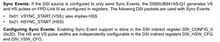
4. 941 dsi timing
Please help to check the splitter mode configuration ,thanks.