This thread has been locked.

If you have a related question, please click the "Ask a related question" button in the top right corner. The newly created question will be automatically linked to this question.

SN65DP159: Device random failure

Part Number: SN65DP159
Other Parts Discussed in Thread: TS3USB221, TPS60151

Hello we have designed a PCI card with two DVI interfaces.

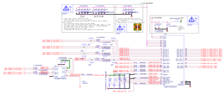
The HDMI signals are generated by an FPGA and they are conditioned using the retimer SN65DP159.

Most card work properly, i.e.: both interfaces provide correct TMDS signals and the monitor displays the image.

In some case, after a period where the card works, one of the two interfaces stops working.

It seems like the retimer stops forwarding the TMDS signals coming from the FPGA.

The two circuits are apparently the same, as shown below

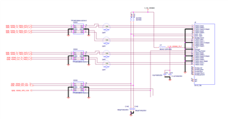
The two DVI interfaces are both sent to two independant DVI connectors, whose scheme is below

In all failure cases the broken interface s always the same, i.e.: the retimer U8.

See also below a detail of the gerber of U8. 

Do you have any hint about where to focus?

Many thanks

Andrea

  • Andrea

    One thing I noticed in your schematic is that you have AC coupling on both side of the TS3USB221. You can have AC coupling capacitors on both side, but you need to provide an external bias 0-3.6V. 

    Do you have a way to bypass the TS3USB221 and see if the issue still there?

    Thanks

    David 

  • Hi thanks for the feedback.

    Could i replace caps with 0r0 resistors.
    Do You have suggestion about what caps should I replace?

    Moreover notice that I have caps on both TS3USB221 devices, the working one and the broken one; and the working one is... working...even with those caps

    Best regards
    Andrea

  • Andrea

    If the FPGA output common mode voltage is within the TS3USB221 spec, then you can remove the AC coupling cap between the FPGA and the TS3USB221. Please also note the TS3USB221 input voltage range is from 0 to 5.5V.

    I understand that you are seeing failure with U8 DP159, but my concern is with the TS3USB221 common mode voltage not being set correctly, anything can happen. So I want to eliminate this possibility for now and then see what happens.

    Thanks

    David

  • ok we replaced C107-C110 and C173-C176 with 0 ohm resistor and situation is very much better: THANK YOU!

    now the output is displayed on the monitor, but the image is flickering.

    Any idea?

  • Andrea

    1. Are you configuring the DP159 in I2C or pin-strap mode? For I2C mode, can you please send me a dump of the DP159 registers?

    2. Can you probe both the DP159 input and output clock using a scope?

    Thanks

    David 

  • the DP159 has pin 8 set to logic 1 with a 10k pullup (I2C control mode), and actually we saw I2C traffic over pin 13 and 14 (I2C CTL port).

    For the scope we'll provide tomorrow.

    Now we are trying to replace the zero ohm with 22 to 50 ohm, in order to damp the signal a little bit. I'll keep you informed

  • Andrea

    The DP159 control pins requires 65k pullup/pulldown, but are you programming the DP159 registers or just leave them the default value? 

    You can also have DP159 pin 8 pulled low (pin-strap mode), and leave PRE_SEL, EQ_SEL, and SLEW_CTL all NC and see if it solves your flicking issue.

    Thanks

    David 

  • Hello

    Also by mounting 65k pull down the flickering is not solved

    A bit of information more: our customers is using an active dvi cable and he says that after 10min the 5V on the dvi  connector is no longer present. 

    We are using a couple if Tps60151 charge pump converter to generate the 5v used for each dvi connector

    Any clue? 

    Thanks! 

  • Andrea

    For the video flickering, are you leaving PRE_SEL, EQ_SEL, and SLEW_CTL all as NC? Does it happen with all video resolutions or just a particular video resolution?

    For the question on TPS60151, I forwarded this thread to our power management group and ask for their input.

    Thanks

    David

  • Hi David,

    actually not yet: i set a 65k pulldown on pin-strap mode, and left existing pulls on other control signals.

    I will check results by removing all bias on the other ctrls, and will let you know

    br

    A

  • Hi Andrea,

    Our group supports TPS60151.  Could you share your schematic, and any captured key waveforms of the TP60151?  

    Thanks,

    Youhao

  • Hello David, situation became a bit worse, because we tried to mount a small coax connector between clk+/- to probe the clock signal as best as possible, but after this operation output is no longer existing (black screen)

    It seems like the retimer no longer forward the signals to the DVI connector.

    We see the signals and clock at the retimer input, but zero at its output.

    We undo the connector mounting trying to restore as best as possibile existing connection (also by replacing the AC caps with fresh ones), but stil nothing is presented at the retimer output.

    Please could you suggest why the retimer refuses to forward the TMDS signals to the DVI connector?

    Boundary conditions:

    setting I2C_EN low with a 65K and leaving other conf pin floating do not change situation

    we measured the 1.1V and 3.3V supplies and they seem ok

    OE seems ok (logic 1)

    clock and DVI are measured and detected as present at retimer inputs

    HPD is correctly forwarded from the DVI connector to the retimer output (pin 3)

    We see I2C activity on I2C CTL interface (not yet succeeded to dump the retimer register file - will provide asap) - (pin 13 14)

    We don't see any activity on I2C DDC interface (SRC/SNK) - (pin 32 33 38 39)

    many thanks

    Andrea

  • hello David

    the DP159 is directly driven by an FPGA (interfacing hi speed transceiver), in turn managed by a CPU via pci express.

    The configuration of the retimers is thus performed by a piece of vhdl,as shown below

    if (DP159_VERBOSE)
    xil_printf("DP159 HDMI 2.0\n\r");
    r = i2c_dp159_write(DP159_ES, 0x0A, 0x36); // Automatic retimer for HDMI 2.0
    r = i2c_dp159_write(DP159_ES, 0x0B, 0x1a);


    r = i2c_dp159_write(DP159_ES, 0x0C, 0xa1);
    r = i2c_dp159_write(DP159_ES, 0x0D, 0x00);

    if (DP159_VERBOSE)
    xil_printf("Retimer for HDMI 2.0 complete\n\r");
    }

    best regards

    Andrea

  • Andrea

    This is a DVI design, why do you have code for HDMI2.0? 

    It looks like you are trying to force the TMDS_CLK_RATIO_STATUS to be 1 for HDMI2.0. Normally the DP159 will snoop the DDC bus between the FPGA and the monitor. When the FPGA and the monitor communicate HDMI2.0, the DP159 will automatically set the TMDS_CLK_RATIO_STATUS to 1. Are the FPGA and the monitor communicate HDMI2.0 across the DDC bus?

    For DVI application, I will probably set the pre-emphasis to 0dB in register 0x0C.

    When you measure the DP159 output, do you have external 50ohm to 3.3V? If you have external 50ohm to 3.3V, and still do not see a clock output, then I will probably replace the DP159.

    Thanks

    David  

  • we acquired a VHDL HDMI core for a kintex-7 FPGA together with a reference design, making use of DP159 retimer.

    We had to move to DVI connector because of customer requirement, by only changing the connector, because customer has to use an active optic DVI converter (Opticis M1-1000).

    As said, we dont see any activity on DDC bus

    As for the termination, i didnt understand: are they needed only for probing? Or are they required at design level?

    Be aware that when we had board working we were able to probe the TMDS signals without any termination. 

    as for the pre-emphasis

    would you suggest to move as follow?

    r = i2c_dp159_write(DP159_ES, 0x0C, 0x00);

    any other suggestion on the other register?

    best regards

    Andrea

  • hello we want to replace the DP159, but we are not finding any stock anywhere.

    Could i use DP149 as a replacement? 

    A

  • Andrea

    Yes, you can replace the DP159RSB with DP149RSB. Please note the DP159 supports HDMI2.0 while the DP149 supports HDMI1.4 only.

    Thanks

    David

  • Hello David

    we finally replaced DP149RSB instead of DP159 and both interfaces are now working properly.

    Question #1:
    FW is still the original, i.e.: trying to configure retimers as HDMI2.0:

    r = i2c_dp159_write(DP159_ES, 0x0C, 0xa1);

    I suppose the DP149 ignores this setting, am i right?

    Question #2:

    Am i still able to have 4K output also with DP148?


    best regards

  • Andrea

    Register 0x0C changes the TX VSWING and post cursor, and it is the same between the DP149 and DP159, so the write to DP159 will also apply to the DP149.

    The DP149 can only support up to 3.4GHz, so it can support 4096×2160 at 24 Hz, 3840×2160 at 24, 25, and 30 Hz, and 1920×1080 at 120 Hz but it will not able to support 4k@60Hz as the bandwidth is outside of its supporting range.

    Thanks

    David