Because of the Thanksgiving holiday in the U.S., TI E2E™ design support forum responses may be delayed from November 25 through December 2. Thank you for your patience.

This thread has been locked.

If you have a related question, please click the "Ask a related question" button in the top right corner. The newly created question will be automatically linked to this question.

SN65DSI84: How to set the output waveform of LVDS through registers

Part Number: SN65DSI84

Hi Sir,

Our customer has a question for the using of SN65DSI84, that is, how to set the output waveform of LVDS through the register. They have tested the point on LCM when the screen is lighting up, and the measured output waveform of Channel A is as follows:
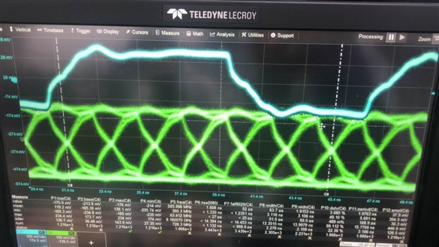
From the waveform we can learned that the output waveform of the test data is triangular. So our customer wants to know whether the output waveform can be optimized by modifying the relevant register parameters of SN65DSI84. Can u help to give us some suggestion for this problem?

Thanks,

Best Regards

  • Hi,

    You can't change the output waveform, you can only configure the DSI84 LVDS output common mode and SWING voltage.

    Thanks

    David 

  • Hi David,

    Thanks for your reply, but we have two more questions as follows:

    1) Which registers need to be set to modify the DSI84 LVDS outout common mode?

    2) Which registers need to be set to modify the SWING voltage?

    Best Regards,

    Lumina

  • Lumina

    Both common mode and SWING voltage are set through register 0x19, you can further adjust the common mode voltage through register 0x1B.

    Thanks

    David

  • Hi David,

    Thanks a lot for your reply. But our customer still some questions as below:

    Did the 0x1B register could be written? If yes, can u provide some suggestion for it? We have tried to set the value of the 0x1b register, but failed. The detais are as below.

    To modify the void sn65dsi84_on(void) function, the code is as follows:

    if (cmds && cmd_cnt > 0) {
    int i, ret;
    pr_err("====cmds && cmd_cnt > 0====\n");
    for (i = 0; i < cmd_cnt; ++i) {
        struct sn65dsi_reg_hdr cmd = cmds[i];
        if(cmd.addr == 0x19)
            ret = sn65dsi84_reg_write(client, 0x19, 0x4f);
        else if(cmd.addr == 0x1b){
            ret = sn65dsi84_reg_write(client, 0x1b, 0x40);
            if (ret <= 0)
            pr_err("====%s: fail to write addr: 0x1b value: 0x40\n", __func__);
        else
            pr_err("====%s: success to write addr: 0x1b value: 0x40\n", __func__);
            }
    else
        ret = sn65dsi84_reg_write(client, cmd.addr, cmd.value);
    pr_err("====cmd.addr:0x%x cmd.value:0x%x====\n",cmd.addr,cmd.value);
    

    From the printed log information, it shows that the value of the 0x1b register has been modified successfully.

    01-16 19:41:38.186     0     0 E ====sn65dsi84_on: success to write addr: 0x1b value: 0x40

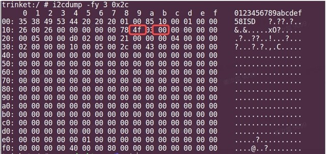
    But when we use the i2c dump command to verify the result and noticed that the 0x19 register value have changed, but the 0x1b register value is still 0x00, which indicating that the 0x1b register is written fail.

    Thanks,

    Best Regards

  • Hi,

    Can they measure the actual output common mode voltage to see if the writing to register 0x1B takes effect? 

    When 0x19.6 = 1 and 0x1B.5:4 = 11 the common mode voltage will be ~1V and when 0x19.6 = 0 and 0x1B.5:4 = 11 the common mode voltage will be ~1.3V.

    Thanks

    David