This thread has been locked.

If you have a related question, please click the "Ask a related question" button in the top right corner. The newly created question will be automatically linked to this question.

SN65176B: I inquire about fail safe resistors, VAB and nUL

Part Number: SN65176B

Hello, 

I inquire about fail safe resistors, VAB and nUL, which is the ratio of the common-mode resistance of one unit load to the common-mode resistance of the transceiver unit load.

Currently, we are using the RS-485 communication circuit as follows.

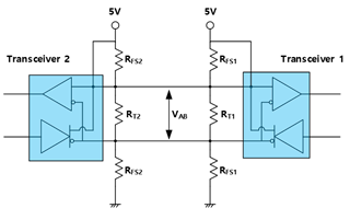
One-to-one communication is applied, and the RFS and RT values of each transceiver are as follows.


RFS

RT

VAB

Transceiver 2

500Ω

120Ω

0.464V

Transceiver 1

620Ω

120Ω

Transceiver 1 uses the MAX491 and Transceiver 2 uses the SN65176B.

When the circuit is configured as above, the VAB voltage is output over 400mV.

When the fail safe resistor is equalized, RFS = RF1 // RFS2 < 375Ω, which is lower than the RCM voltage, and the maximum number of transceiver, n, has a negative value.

www.edn.com/.../
* equation 7

There are my Questions,

Q1. What kind of problem occurs when the VAB voltage value in idle state is output over 400mV?

Q2. What happens when the value of n (Maximum number of transceiver) is negative? Is it okay if the value of n is negative?

Best Regards

  • 1. The differential voltage must be at least 200 mV. You can increase the fail-safe resistors to 1 kΩ. (And check whether you really need fail-safe resistors at both ends.)

    2. This is not OK; it means that there is not enough drive strength for even a single transceiver.

  • Elaborate a little more on question 2. The maximum bus load is 375Ohm. Negative n means RB is to small => RB itself exceeds the max load. 

  • Hello, Thanks for your Reply

    Then,  I'd like to ask some questions, below

    Q1. What is the maximum value of the  differential voltage, VAB? 

    Q2. As shown in the figure above, when RT and RFS are selected as 12Ω and 620Ω, respectively, VAB voltage of 400mV or more is output in simulation.

           What problems arise when RT and RFS are selected as above? can i use it?

    Best Regards

  • 1. As shown in the recommended operating conditions, the maximum for this receiver is ±12 V. Other receivers have similar limits. In practice, you do not need to care about the maximum because it's larger than the supply voltage.

    2. In the idle state, any voltage larger than 200 mV is OK. (But you have to check all three states: idle, A<B, A>B).

  • What does it mean to check the three states? Are you talking about idle state, A to B, B to A communication?

  • I mean the A/B pins. RFS pulls A high and B low; when the transmitter is active and D is low, it drives A low and B high. If RFS are too strong, the differential output voltage might be too low.

  • Hi Lee,

    Clemens is correct on his analysis.

    When you are checking the three states, you are verifying that the input voltage is valid when the bus:

    Communicates from A to B

    Communicates from B to A

    And when the bus is idle.

    When you have these numbers you can compare them to the datasheet to see if you are able to reach valid 1 or a valid 0 when A communicates to B, when B communicates to A and that the bus is a defined state when Idle.

    Please let me know if you have any other questions!

    Best,

    Parker Dodson