Because of the Thanksgiving holiday in the U.S., TI E2E™ design support forum responses may be delayed from November 25 through December 2. Thank you for your patience.

This thread has been locked.

If you have a related question, please click the "Ask a related question" button in the top right corner. The newly created question will be automatically linked to this question.

TLK10031: Configurating XAUI to 10GBASE-SR(SFP+) mode

Part Number: TLK10031

Hello,

We are trying to configure TLK10031 in XAUI to 10GBASE-SR(SFP+) mode by following below procedure(which we found from other TI threads)

1. Reset device (write a 1 to 0x1E.0000 bit 15 or assert RESET_N pin)
2. Make sure the reference clock selection (156.25 MHz or 312.5 MHz) is correct – this is done through register 0x1E.001D bit 12 (default is 156.25 MHz).
3. Disable auto-negotiation by writing 1’b0 to 0x07.0000 bit 12
4. Disable link training by writing 16’h0000 to 0x01.0096
5. Write 16’h03FF to 0x1E.8020. This allows the link settings that would normally be configured through KR training to be configured manually instead.
6. Depending on the link conditions, you may need to change the default configuration of 0x1E.0003 and 0x1E.0004. For optical connections, we typically recommend changing HS_ENTRACK (0x1E.0004 bit 15) to 1’b1 and HS_EQPRE (0x1E.0004 bits 14:12) to 3’b101. This can be a starting point, but you may need to do some BER testing to optimize the values.
7. Issue a data path reset by writing 1’b1 to 0x1E.000E bit 3. 

8. Repeat Step 7(data path reset)

But the link is not establishing between our system and TLK10031.

Our application setup is like this
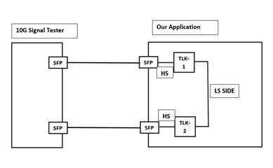
As you can in the image, we are using two TLK10031 in our application. LS side of both TLK's are shorted and HS side of both TLK are connected to SFP+ ports. We have connected optical cables between 10G signal tester and our application device in loopback fashion as it can be seen in image.

After following the above 8 steps for both the TLK's, still link is not getting established between 10G tester and our device.

I am mentioning few Status and Error counter registers readings(readings are coming same for both TLK_1 and TLK_2)

CHANNEL_STATUS_1 = 0X1C03

HS_ERROR COUTER = Varies between 0xF7E0 to 0xF8FF

LS_LN0_ERROR_COUNTER = 0x0000

LS_LN1_ERROR_COUNTER = 0x0000

LS_LN2_ERROR_COUNTER = 0x0000

LS_LN3_ERROR_COUNTER = 0x0000

LS_STATUS_1 = Varies 0x8800 to 0x8810

HS_STATUS_1 = 0xF005, 0XF008, 0XF02A(varies between these 3)

PCS_STATUS_1 = 0x8801

AN_CONTROL = 0X2000

LT_TRAIN_CONTROL = 0X0000

Please suggest us what to do to resolve this issue.

And please explain me about step 6 i.e. 

6. Depending on the link conditions, you may need to change the default configuration of 0x1E.0003 and 0x1E.0004. For optical connections, we typically recommend changing HS_ENTRACK (0x1E.0004 bit 15) to 1’b1 and HS_EQPRE (0x1E.0004 bits 14:12) to 3’b101. This can be a starting point, but you may need to do some BER testing to optimize the values.

If possible please suggest me any other combination for 0x1E.0003 and 0x1E.0004 that may works for my application.

Thank You in advance.

Regards

Balaji TS

  • Request noted. I will target to provide feedback within next couple of days.

    Thanks,

    Rodrigo Natal

  • Thank you Rodrigo Natal,

    We hope soon we will get some help from your side. Meantime we will try by our own with different combinations.

    Thank you in advance.

  • Hi Rodrigo Natal,

    Any suggestions for query? 

    We have tried many combinations of HS_SERDES_CONTROL_2 and  HS_SERDES_CONTROL_3 register. But still we are not able to establish the link.

    Is there any specific document for configuring TLK10031 in 10GBASE-SR mode as i didn't found full details in TLK10031 datasheet. We referred many previous threads regarding 10GBASE-SR(Fiber optic) configuration and followed the procedure recommended by TI experts but still not able solve the problem.

    Please help us to resolve this issue.

    Awaiting for your response.

    Found only this information in datasheet regarding 10GBASE-SR mode configuration.

    The TLK10031 device can be used to convert between XAUI (on the low speed port) and 10GBASE-R
    signaling (on the high speed port). The high speed side of the device meets the requirements of the
    10GBASE-KR physical layer standard for 10 Gbps data transmission over a PCB backplane. The device
    can also be used for optical physical layers (like 10GBASE-SR or 10GBASE-LR) by interfacing to optical
    modules requiring SFI or XFI electrical signaling. For optical use cases, KR-specific features like Clause
    73 auto-negotiation and link training should be disabled.

    Thank You. 

  • Hi Rodrigo Natal,

    Our issue is resolved, we are able achieve the link successfully. With previous settings we disabled PRBSEN pin, so our device got proper link with HS and LS errors as 0.

    But we have one doubt, we have a Link/Activity LED on our board. We wants to blink activity LED when data transfer happens through our link. How do we get to know that does our link is idle or data transfer is happening. Is there any Pin or Register in TLK10031 indicates the activity of our link?

    Thank you in advance.

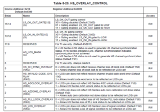
  • You should be able to use the TLK LOS pin as more of a global status indicator, and the LOS status gating parameters can be configured via MDIO registers (see datasheet table below for ease of reference). Refer to the TLK datasheet for further details.

    Thanks,

    Rodrigo Natal

  • Thank You Rodrigo Natal for your suggestion,

    We will work on it. 

    Thank you.