This thread has been locked.

If you have a related question, please click the "Ask a related question" button in the top right corner. The newly created question will be automatically linked to this question.

TCAN1044AV-Q1: standby mode issue

Part Number: TCAN1044AV-Q1

Hi Sir,

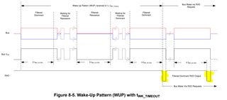
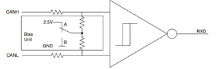
My customer meet a problem with the standby mode, why the RXD is providing the incorrect waveform after engine-ON?

Why are there not see any wake-up waveform? cause the system can not going to the normal mode.

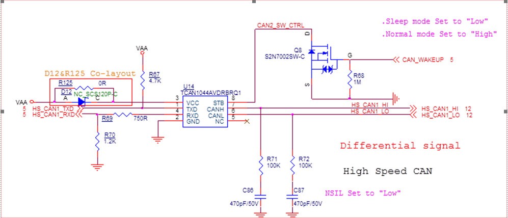
Could you please check the below schematics is correct or not?

(VCC=5V, VIO=5V, VAA=3.3V; VCC & VIO & VAA are exist and the STB used the internal pull-up on the standby mode)

engine OFF_STB and RXD: (into standby mode)

engine ON_STB and RXD: (keep on standby mode)

engine ON_CAN_H and RXD: (keep on standby mode)

  • Hi Henry,

    I'm not sure I fully understand the issue you describe here. It sounds like perhaps the system is reporting bad CAN data from the RXD line. Is this correct?

    The schematic here looks a bit odd. The transceiver is labeled as a TCAN1044AV, but pin 5 is shown as a NC and is not connected to any net. Pin 5 of TCAN1044AV is the Vio supply input and is required for normal operation of the device. Is this correct? If this schematic is true, I would expect the transceiver to not work at all. 
    Other odd things include the pull-down on the RXD line. The RXD signal will rest at logic high (recessive) for any idle condition, including while the transceiver is in Standby mode before receiving a WUP. Is there a specific reason why this signal is biased low? 
    The STB input has an internal pull down. The schematic shows there is no way for this signal to be pulled-high as it is driven by an external open-drain. Is there an external pull-up on this signal line? What is the reason why the CAN_WAKEUP signal being inverted before going to the transceiver?

    The waveforms here look normal to me. Nothing here shows any behavior that I would not expect:
    1. While STB is high, the transceiver is in Standby mode. RXD will remain high until the transceiver recognizes a wake up pulse (WUP) on the CAN bus. 
    2. While STB is low, the transceiver is in Normal mode. RXD will reflect the state of the bus, thus we see CAN data show up here on channel 1. 
    3. Here we see the RXD pin reflecting the data on the CAN bus. It's a bit difficult to see with the large timescale, but I don't see any places where the data here looks corrupted. 

    Regards,
    Eric Schott

  • Hi Sir,

    I'm sorry, I didn't clearly inform the current schematics.

    I'm sure my customer is using the TCAN1044AV-Q1 now, the schematic is not modified to the correct pin-name yet.

    VCC=5V, VIO=5V, VAA=3.3V; VCC & VIO & VAA those power still existed on the Standby mode.

    So, the CAN_WAKEUP signal(from the MCU) is kept a low level before receiving a WUP.

    Could you please check the STB is an integrated pull-up or pull-down? the TCAN1044AV-Q1 datasheet is mentioned the pin is an integrated pull-up.

    My customer asks the RXD why has it not received a wake-up pulse (WUP) on the CAN bus after the car engine-ON? it's shown in figure9-5 on the TCAN1044AV-Q1 datasheet.

    Why is the STB pin kept high level(standby mode), the RXD will provide below waveform after the car engine-ON?

  • Hi Henry,

    Thanks for the clarification on the schematic. You are correct that the STB pin has an integrated pull-up, this was my mistake earlier. 

    When the transceiver is in Standby mode (STB=1), any WUP will cause the RXD pin to pull low after the bus remains dominant for t > tWK_FILTER. This is how the transceiver indicates to the controller that there is activity on the CAN bus and that it should be placed into Normal mode (STB=0) in order to interface with the bus. When the bus goes recessive (logic high), this timer resets and RXD will go low again once a dominant period (logic low) persists on the bus for t > tWK_FILTER. This may make it appear that RXD is fully active while the transceiver is in Standby mode, but this is still only the transceiver's indication to the controller that there is activity on the CAN bus. 

    Let me know if I've understood this situation correctly. 

    Regards,
    Eric Schott

  • Hi Sir,

    Yes, we understood your description.
    My customer's question why do they never see the RXD pin send a request waveform after the auto engine-ON?
    They think the waveform on the RXD pin is like the communication messages.
    Do you think cause the main system has not sent a WUP to the transceiver, right?

  • Hi Henry,

    In the last waveform you shared, we can see that the RXD pin goes low while STB remains high. This is the transceiver indicating that it has received a WUP. The low period on RXD only lasts until the bus goes recessive again. This means that when CAN data shows up on the bus, the RXD pin can pulse depending on the data contents. This behavior is the indication to the CAN controller that the bus is active and it should put the transceiver into normal mode. 

    Keep in mind that any valid CAN frame will contain the conditions for a WUP. So any CAN data will also wake the transceiver and cause RXD to assert to notify the controller.

    Is this different from what the customer expects to see in their system? 

    Regards,
    Eric Schott

  • Hi Sir,

    My customer ask why the CANH/L still have 2-V output voltage at the auto engine-off into STB mode?

    They have tried to remove the TCAN1044AV-Q1 after the auto engine-off into STB mode, the CANH/L signal traces can be pulled down to 0V.

    Is this different from what the customer expects to see in their system?  => Why there can not see the RXD send a request waveform shown as below? They only see the RXD send the waveform like as the CAN frame. So the MCU cannot recognize the wake-up event and pull down the STB pin to let the CAN transceiver into the normal mode.

  • Hi Sir,

    Any update?

  • Hi Henry,

    The 2.5V bias on the CAN bus will be applied by any active CAN transceiver. In this case, I suspect either 1) a secondary transceiver is active on the bus and biasing it to 2.5V, or 2) TCAN1044A is not fully in Standby mode (STB = low) and therefore has its recessive bias active. The reason why the bus voltage is 2.0V is because some leakage path exists which is pulling down the 2.5V bias - this is likely caused by some inactive transceiver (CAN pins weakly biased to GND). 

    The data that appears on the RXD pin does not fully represent the CAN bus state. Because there is some minimum dominant time (tWK_FILTER) before the RXD pin responds to a dominant state, this signal will always have a very delayed R>D response. The intention of this response is not to propagate CAN data, but simply to indicate that there is activity on the CAN bus. The MCU may be programmed to trigger on any transition detected on the RXD in order to wake up. The MCU should then assert STB = high to properly interface with the CAN bus. 

    Regards,
    Eric Schott