This thread has been locked.

If you have a related question, please click the "Ask a related question" button in the top right corner. The newly created question will be automatically linked to this question.

TCAN332: Un-intended GND path through CAN H/L pins

Part Number: TCAN332
Other Parts Discussed in Thread: BQ76940

Hello Everyone!

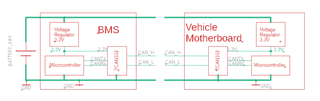
I am from Delhi, India and we work on low-power e-scooters. We are using TCAN332 CAN transceivers on all the nodes in our e-scooters. We have a BMS (High side switching, in-house design using BQ76940) and a Vehicle motherboard. The scooter facilitates a ‘swappable battery' architecture. The entire system has been running fine for a few months now. Please refer to Fig. 1 below for a broad outline of the system (for simplicity, I have omitted unnecessary details on the BMS and Motherboard):

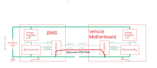
Recently I have noticed that if somehow, the GND pin is left unconnected (Faulty wire or misaligned battery connector) or other pins connect first and the GND pin connects in the end, then the CAN transceivers on both boards fry/blow up, everything else remains undamaged. I suspect that The CAN H and CAN L pins provide an ‘alternate return path’ to the GND, as shown in fig. 2 below:

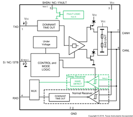
This hypothesis comes from the internal block diagram of the TCAN332 IC as given in the datasheet (Fig.3 below):

Please let me know if I understand this correctly. Also, please help me with any possible solutions to this problem. I want the system to be fail-safe in such cases.

Thanks in Advance.

  • Hi Battery Ninja,

    Thanks for bringing your question to E2E. 

    My first thought here would be that some voltage on the CAN bus would exceed the transceiver's limits and cause it to break. The absolute maximum voltage that the CAN pins can tolerate is ±14V with respect to GND. With GND floating, it's hard to say what the applied voltage would actually be, but with a battery level of 60V it sounds like it would be quite easy to exceed this ±14V range between the two boards. 

    To avoid this problem, there are a few approaches that you could take. One common method is to ensure that the GND connection is always made first by using a connector with slightly longer GND than other pins so that it always connects first when plugging and last when unplugging. Similarly, the two boards could also share a chassi ground or shielded ground (often connected to external metal frames) through some high resistance path. This gives both boards a method of discharging to a common ground even when they are not connected directly. Lastly, you may consider including protection devices along the CANH and CANL nets on each board to help dissipate or block transient energy during connection events. This would primarily include TVS diodes, but may also be PTC fuses and bus capacitors. Let me know if you have any questions on these components or how to select appropriate values. 

    Regards,
    Eric Schott

  • Hi Eric,

    Thanks for the prompt reply. The kind of connector which we're using here indeed has a longer GND pin. I just wanted to eliminate the tiniest possibility of this issue.

    Here, grounding the Chassis isn't an option for us since the part of the battery which is in contact with the vehicle is plastic.

    We also tried Putting Bidirectional TVS diodes on both the CAN lines (SMAJ6.0CA), on both the boards. Also, these boards already have CAN ESD protection (SZNUP2105) on them. This has helped in making the lines more robust. Now Even with GND floating, TCAN332 is safe most of the time, but the TVS diodes themselves get fried.

    Please let me know if the choice of TVS diodes here is right. Also, Since TVS diodes of much higher power (SMAJ6.0CA) are connected here, do we still need to put the ESD protection diodes (SZNUP2105) here? Or can we simply remove them and depend on SMAJ6.0CA for ESD protection as well?

    Also, I would like to know more about how PTC fuses and bus capacitors would help in this case. 

  • Hi Ninja,

    I'm glad to hear that you are seeing some success with the TVS diode implementation. The important factors to consider when selecting these components is that the breakdown voltage is outside of the normal operating conditions of the system (for CAN > 5V) and that the clamping voltage is less than the abs max of the transceiver pin (14V in this case). For this, your selection of the SMAJ6.0CA is a fine choice, though it sounds like the power presented by the event can still be a bit much for it. 

    In addition to shunting the extra energy from the event with a TVS diode, a blocking device such as a PTC fuse can act to protect the TVS diode once it engages. A Positive Temperature Coefficient (PTC) fuse increases in impedance when more current passes through it. This allows it to act as a short circuit during normal operating conditions and an open circuit during fault conditions. Once the fault is removed and the component cools down, it becomes a short circuit again to allow normal operation to resume. These devices can limit the amount of energy a shunting device needs to dissipate as it only needs to conduct until the PTC fuse has time to react and go high-Z. The rest of the energy is dissipated more slower through the fuse and allows more time for all of the components to stay cool. 

    Similarly, bus capacitors can help smooth fast transients and decrease the max peak power of a ESD or surge event. This is typically less effective than dedicated protection devices, but it's a relatively simple and inexpensive way to increase immunity to harsh transients. For CAN we typically recommend bus capacitor values between 10pF and 150pF to help filter out high frequency noise and lengthen transient pulses. These should be placed on both CANH and CANL to GND. 

    Let me know if you have more questions on these protection methods. 

    Regards,
    Eric Schott

  • Hi Eric,

    This was really informative, thanks for sharing.