This thread has been locked.

If you have a related question, please click the "Ask a related question" button in the top right corner. The newly created question will be automatically linked to this question.

TCAN4550: Data loss when transmitting with a delay less than 100ms, and SPI ERR is always set even when the transmission is happening.

Part Number: TCAN4550

Hello

I’m Sanskar Verma, And I’m facing issues while developing a product using TCAN4550 for CAN-FD.

I am able to transmit and receive data with a delay of 1000 ms but if i am lowering the delay to 100 ms or below, all data packets don't reach the receiver. There is a significant loss of data while transmitting with a delay of less than 100ms.

I am able to receive all the data if there is a delay of 1000ms or more in CAN_Transmit. but my application demands no delay in transmission. I want to continiously transmit and recieve data from multiple nodes.

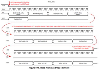
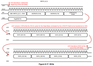
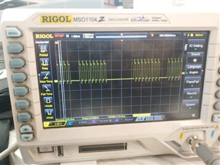
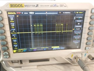
i'm attaching the all the 4 waveforms of SPI communication and the values of the registers 0x000c, 0x820, 0x0824, 0x0830 for your reference. Please look into it and let me know if you want any more information from my side.

CLK       nCS

CLK  CLK

    MISO

MOSI MOSI

Values of registers

0x000C = 30000a / 20000a / 8 / 804000e  (these values keep fluctuating randomly)

0x820 = 88 / 8a (these values appear mostly)

0x824 = 10105

0x830 = 809628ff

0x0800 = c84004a0

  • Sanskar,

    I've notified one of our experts of this thread and they will respond after the weekend. We really appreciate your patience here.

    Regards,

    Eric Hackett 

  • Hi Sanskar,

    I would be glad to help, can you give me some additional information?

    Are you using an Evaluation Board from TI, or are have you developed your own board already?  If you have developed your own board, would you mind sharing the schematics regarding the TCAN4550 circuit?

    What microprocessor are you using, and are you using the demo code provided with the TCAN4550, or have you developed your own firmware and drivers?

    What is the SPI data rate?  It looks to be approximately 3 Mbps from the CLK waveform.  Is that correct?

    The picture of your nCS waveform looks the same as the CLK waveform.  Can you provide a plot of the nCS so or verify it is High between SPI transactions?

    Can you provide a zoomed out image to capture the complete SPI data transmitted between nCS falling Low, and then going High again?  We need to verify there is the proper number of bits.  The TCAN4550 checks for the correct number of bits in a SPI transaction and it will generate a SPI error if it is not correct.  These bits are getting set in the Status register, so we need to figure out why.  How many bits are you transmitting between the nCS falling and rising edges?

    For register 0x820 value 0x88, this is a SPI Error and then the Global Error which is also set for any error including the SPI error.  For value 0x8A, this has the  M_CAN interrupt set which is likely indicating you have received a message.

    For register 0x824 value 0x10105, you have the RF0W and RF0L set indicating that your RX FIFO watermark was reached and that you have lost a message.  This is generally because your RX FIFO does not have enough elements to store the messages it has received to give time for the processor to read them out of memory and free up the RX FIFO element for a new message.  If the RX FIFO gets full, new messages are either rejected, or overwritten depending on your configuration.  If a message gets lost for either of these situations, the RF0L bit gets set.

    Can you also provide the values of your CAN controller configuration registers as well? These are the registers with an address of 0x1000 and greater.  I would like to see how you have configured your CAN controller such as how many elements you have in your RX and TX FIFOs and or buffers, etc.

    I suspect there are one or two different issues here based on the information you have provided so far.  The first is there appears to be some issue with your SPI driver generating errors.  If there is an error on writing SPI data, then the TCAN4550 discards the transaction, and this could lead to delays and corrupted configuration registers and CAN message data.

    The second issue is that your CAN controller and MRAM space may not be setup properly for your application and you may need to adjust your RX FIFO size to prevent losing messages.

    If you have not read our Software User's Guide, I would suggest you to look at it because it discusses how to configure the device.  You can find it at this (link).

    Regards,

    Jonathan

  • Hi Jonathan,

    I have attached the zoomed out image to capture the complete SPI data transmitted between nCS falling Low, and then going High again.

    SPI Data rate is 3mbps and i am transmitting 32 bits between the nCS falling and rising edges.

    Value of Registers while  transmitting data at a delay of 1000ms

    0x0820=4a0

    0x000C=8

    0x0824=10000

    Value of Registers while  transmitting data at a delay of 10-100ms or below

    0x0820=0

    0x000C=8

    0x0824=10000

    Can you emphasize more on the CAN SILENT flag and in which cases it is set to high.

    I have attached the code from my TCAN4550.c file so that you can check up  the configuration of MRAM.

    /*
    * TCAN4550.c
    * Description: This file contains TCAN4550 functions, and relies on the TCAN4x5x_SPI abstraction functions
    * Additional Feature Sets of TCAN4550 vs TCAN4x5x:
    * - Watchdog Timer Functions
    *
    * Version: 1.2.0
    * Date: 5/1/2019
    *
    * Change Log
    * 1.2.1 (9/19/2019)
    * - Added a missing AHB_BURST_READ_END() to the TCAN4x5x_MCAN_ReadXIDFilter function, which caused the next read or write to fail
    *
    * 1.2.0 (5/1/2019)
    * - Added the MCAN_ConfigureGlobalFilter function for changing default packet behavior
    * - Added a define to allow caching of MCAN configuration registers to reduce the number of SPI reads
    * - Added a FIFO fill level checker to the MCAN_ReadNextFIFO method to exit if there is no new element to read
    * - Added a read function for SID and XID filters
    * - Added a SPIERR clear function
    *
    * 1.1.1 (6/12/2018)
    * - Minor typo correction for the ConfigureNominalTiming_Simple() function
    *
    * 1.1 (6/6/2018)
    * - Updates to code for readability, and consistency
    * - Some function names updated for consistency
    * - Added functionality and abstraction for interrupts
    * - Bit fields updated for final silicon
    *
    *
    * Copyright (c) 2019 Texas Instruments Incorporated. All rights reserved.
    * Software License Agreement
    *
    * Redistribution and use in source and binary forms, with or without
    * modification, are permitted provided that the following conditions
    * are met:
    *
    * Redistributions of source code must retain the above copyright
    * notice, this list of conditions and the following disclaimer.
    *
    * Redistributions in binary form must reproduce the above copyright
    * notice, this list of conditions and the following disclaimer in the
    * documentation and/or other materials provided with the
    * distribution.
    *
    * Neither the name of Texas Instruments Incorporated nor the names of
    * its contributors may be used to endorse or promote products derived
    * from this software without specific prior written permission.
    *
    * THIS SOFTWARE IS PROVIDED BY THE COPYRIGHT HOLDERS AND CONTRIBUTORS
    * "AS IS" AND ANY EXPRESS OR IMPLIED WARRANTIES, INCLUDING, BUT NOT
    * LIMITED TO, THE IMPLIED WARRANTIES OF MERCHANTABILITY AND FITNESS FOR
    * A PARTICULAR PURPOSE ARE DISCLAIMED. IN NO EVENT SHALL THE COPYRIGHT
    * OWNER OR CONTRIBUTORS BE LIABLE FOR ANY DIRECT, INDIRECT, INCIDENTAL,
    * SPECIAL, EXEMPLARY, OR CONSEQUENTIAL DAMAGES (INCLUDING, BUT NOT
    * LIMITED TO, PROCUREMENT OF SUBSTITUTE GOODS OR SERVICES; LOSS OF USE,
    * DATA, OR PROFITS; OR BUSINESS INTERRUPTION) HOWEVER CAUSED AND ON ANY
    * THEORY OF LIABILITY, WHETHER IN CONTRACT, STRICT LIABILITY, OR TORT
    * (INCLUDING NEGLIGENCE OR OTHERWISE) ARISING IN ANY WAY OUT OF THE USE
    * OF THIS SOFTWARE, EVEN IF ADVISED OF THE POSSIBILITY OF SUCH DAMAGE.
    */

    #include "TCAN4550.h"

    volatile int8_t TCAN_Int_Cnt = 0; // A variable used to keep track of interrupts the MCAN Interrupt pin
    uint8_t unique_ID_G = 0x01;
    uint8_t global_ID_G = 0xFF;


    #ifdef TCAN4x5x_MCAN_CACHE_CONFIGURATION
    // If caching is enabled, define the necessary variables
    uint32_t TCAN4x5x_MCAN_CACHE[9];
    #endif

    /**
    * @brief Enable Protected MCAN Registers
    *
    * Attempts to enable CCCR.CCE and CCCR.INIT to allow writes to protected registers, needed for MCAN configuration
    *
    * @return @c true if successfully enabled, otherwise return @c false
    */
    bool
    TCAN4x5x_MCAN_EnableProtectedRegisters(void)
    {
    uint8_t i;
    uint32_t readValue, firstRead;

    firstRead = AHB_READ_32(REG_MCAN_CCCR);
    if ((firstRead & (REG_BITS_MCAN_CCCR_CCE | REG_BITS_MCAN_CCCR_INIT)) == (REG_BITS_MCAN_CCCR_CCE | REG_BITS_MCAN_CCCR_INIT))
    return true;

    // Unset the CSA and CSR bits since those will be set if we're in standby mode. Writing a 1 to these bits will force a clock stop event and prevent the return to normal mode
    firstRead &= ~(REG_BITS_MCAN_CCCR_CSA | REG_BITS_MCAN_CCCR_CSR | REG_BITS_MCAN_CCCR_CCE | REG_BITS_MCAN_CCCR_INIT);
    // Try up to 5 times to set the CCCR register, if not, then fail config, since we need these bits set to configure the device.
    for (i = 5; i > 0; i--)
    {
    AHB_WRITE_32(REG_MCAN_CCCR, firstRead | REG_BITS_MCAN_CCCR_CCE | REG_BITS_MCAN_CCCR_INIT);
    readValue = AHB_READ_32(REG_MCAN_CCCR);

    if ((readValue & (REG_BITS_MCAN_CCCR_CCE | REG_BITS_MCAN_CCCR_INIT)) == (REG_BITS_MCAN_CCCR_CCE | REG_BITS_MCAN_CCCR_INIT))
    return true;
    else if (i == 1) // Ran out of tries, give up
    return false;
    }
    return true;
    }


    /**
    * @brief Disable Protected MCAN Registers
    *
    * Attempts to disable CCCR.CCE and CCCR.INIT to disallow writes to protected registers
    *
    * @return @c true if successfully enabled, otherwise return @c false
    */
    bool
    TCAN4x5x_MCAN_DisableProtectedRegisters(void)
    {
    uint8_t i;
    uint32_t readValue;

    readValue = AHB_READ_32(REG_MCAN_CCCR);
    if ((readValue & REG_BITS_MCAN_CCCR_CCE) == 0)
    return true;

    // Try up to 5 times to unset the CCCR register, if not, then fail config, since we need these bits set to configure the device.
    for (i = 5; i > 0; i--)
    {
    AHB_WRITE_32(REG_MCAN_CCCR, (readValue & ~(REG_BITS_MCAN_CCCR_CSA | REG_BITS_MCAN_CCCR_CSR | REG_BITS_MCAN_CCCR_CCE | REG_BITS_MCAN_CCCR_INIT))); // Unset these bits
    readValue = AHB_READ_32(REG_MCAN_CCCR);

    if ((readValue & REG_BITS_MCAN_CCCR_CCE) == 0)
    return true;
    else if (i == 1)
    return false;
    }
    return true;
    }


    /**
    * @brief Configure the MCAN CCCR Register
    *
    * Configures the bits of the CCCR register to match the CCCR config struct
    *
    * @warning This function writes to protected MCAN registers
    * @note Requires that protected registers have been unlocked using @c TCAN4x5x_MCAN_EnableProtectedRegisters() and @c TCAN4x5x_MCAN_DisableProtectedRegisters() be used to lock the registers after configuration
    *
    * @param *cccrConfig is a pointer to a @c TCAN4x5x_MCAN_CCCR_Config struct containing the configuration bits
    *
    * @return @c true if successfully enabled, otherwise return @c false
    */
    bool
    TCAN4x5x_MCAN_ConfigureCCCRRegister(TCAN4x5x_MCAN_CCCR_Config *cccrConfig)
    {
    uint32_t value, readValue;


    value = cccrConfig->word;
    value &= ~(REG_BITS_MCAN_CCCR_RESERVED_MASK | REG_BITS_MCAN_CCCR_CSA | REG_BITS_MCAN_CCCR_CCE | REG_BITS_MCAN_CCCR_INIT); // Bitwise AND to get the valid bits (ignore reserved bits and the CCE and INIT)

    // If we made it here, we can update the value so that our protected write stays enabled
    value |= (REG_BITS_MCAN_CCCR_INIT | REG_BITS_MCAN_CCCR_CCE);


    AHB_WRITE_32(REG_MCAN_CCCR, value);
    #ifdef TCAN4x5x_MCAN_VERIFY_CONFIGURATION_WRITES
    readValue = AHB_READ_32(REG_MCAN_CCCR);

    // Need to do these bitwise ANDs to make this work for clock stop requests and not trigger a false failure when comparing read back value
    if ((readValue & ~(REG_BITS_MCAN_CCCR_RESERVED_MASK | REG_BITS_MCAN_CCCR_CSA | REG_BITS_MCAN_CCCR_CSR | REG_BITS_MCAN_CCCR_CCE | REG_BITS_MCAN_CCCR_INIT))
    != (value & ~(REG_BITS_MCAN_CCCR_RESERVED_MASK | REG_BITS_MCAN_CCCR_CSA | REG_BITS_MCAN_CCCR_CSR | REG_BITS_MCAN_CCCR_CCE | REG_BITS_MCAN_CCCR_INIT)))
    {
    // If our written value and read back value aren't the same, then we return a failure.
    return false;
    }

    // Check to see if the CSR bits are not as expected, since this can be set by the hardware.
    if ((readValue & REG_BITS_MCAN_CCCR_CSR) != cccrConfig->CSR)
    {
    // Then there's a difference in the CSR bits, which may not be a failure.
    if (TCAN4x5x_Device_ReadMode() == TCAN4x5x_DEVICE_MODE_STANDBY)
    {
    // CSR bit is set due to being in standby mode. Not a failure.
    return true;
    } else {
    // It's not matching for some other reason, we've got a real failure.
    return false;
    }
    }
    #endif
    return true;
    }


    /**
    * @brief Read the MCAN CCCR configuration register
    *
    * Reads the MCAN CCCR configuration register and updates the passed @c TCAN4x5x_MCAN_CCCR_Config struct
    *
    * @param *cccrConfig is a pointer to a @c TCAN4x5x_MCAN_CCCR_Config struct containing the CCCR bit fields that will be updated
    */
    void
    TCAN4x5x_MCAN_ReadCCCRRegister(TCAN4x5x_MCAN_CCCR_Config *cccrConfig)
    {
    cccrConfig->word = AHB_READ_32(REG_MCAN_CCCR);
    }


    /**
    * @brief Reads the MCAN data time settings, using the simple struct
    *
    * Reads the MCAN data timing registers and updates the @c *dataTiming struct
    *
    * @warning This function writes to protected MCAN registers
    * @note Requires that protected registers have been unlocked using @c TCAN4x5x_MCAN_EnableProtectedRegisters() and @c TCAN4x5x_MCAN_DisableProtectedRegisters() be used to lock the registers after configuration
    *
    * @param *dataTiming is a pointer of a @c TCAN4x5x_MCAN_Data_Timing_Simple struct containing the simplified data timing information
    */
    void
    TCAN4x5x_MCAN_ReadDataTimingFD_Simple(TCAN4x5x_MCAN_Data_Timing_Simple *dataTiming)
    {
    uint32_t regData;

    // Read the data timing register
    regData = AHB_READ_32(REG_MCAN_DBTP);

    // These registers are only writable if CCE and INIT are both set. Sets the nominal bit timing and prescaler information
    dataTiming->DataBitRatePrescaler = ((regData >> 16) & 0x1F) + 1;
    dataTiming->DataTqBeforeSamplePoint = ((regData >> 8) & 0x1F) + 2;
    dataTiming->DataTqAfterSamplePoint = ((regData >> 4) & 0xF) + 1;
    }


    /**
    * @brief Reads the MCAN data time settings, using the raw MCAN struct
    *
    * Reads the MCAN data timing registers and updates the @c *dataTiming struct
    *
    * @param *dataTiming is a pointer of a @c TCAN4x5x_MCAN_Data_Timing_Simple struct containing the raw data timing information
    */
    void
    TCAN4x5x_MCAN_ReadDataTimingFD_Raw(TCAN4x5x_MCAN_Data_Timing_Raw *dataTiming)
    {
    uint32_t regData;

    // Read the data timing register
    regData = AHB_READ_32(REG_MCAN_DBTP);

    // These registers are only writable if CCE and INIT are both set. Sets the nominal bit timing and prescaler information
    dataTiming->DataBitRatePrescaler = ((regData >> 16) & 0x1F);
    dataTiming->DataTimeSeg1andProp = ((regData >> 8) & 0x1F);
    dataTiming->DataTimeSeg2 = ((regData >> 4) & 0xF);
    dataTiming->DataSyncJumpWidth = (regData & 0xF);

    if (regData & REG_BITS_MCAN_DBTP_TDC_EN)
    {
    // If TDC is set, then read the TDC register
    regData = AHB_READ_32(REG_MCAN_TDCR);
    dataTiming->TDCOffset = ((regData >> 8) & 0x7F);
    dataTiming->TDCFilter = (regData & 0x7F);
    } else {
    dataTiming->TDCOffset = 0;
    dataTiming->TDCFilter = 0;
    }
    }


    /**
    * @brief Writes the MCAN data time settings, using the simple data timing struct
    *
    * Writes the data timing information to MCAN using the input from the @c *dataTiming pointer
    *
    * @warning This function writes to protected MCAN registers
    * @note Requires that protected registers have been unlocked using @c TCAN4x5x_MCAN_EnableProtectedRegisters() and @c TCAN4x5x_MCAN_DisableProtectedRegisters() be used to lock the registers after configuration
    *
    * @param *dataTiming is a pointer of a @c TCAN4x5x_MCAN_Data_Timing_Simple struct containing the simplified data timing information
    * @return @c true if successfully enabled, otherwise return @c false
    */
    bool
    TCAN4x5x_MCAN_ConfigureDataTiming_Simple(TCAN4x5x_MCAN_Data_Timing_Simple *dataTiming)
    {
    uint32_t writeValue, TDCOWriteValue;
    uint32_t tempValue;

    // These registers are only writable if CCE and INIT are both set. Sets the nominal bit timing and prescaler information
    // Check to make sure prescaler is in range 1-32
    tempValue = dataTiming->DataBitRatePrescaler;
    if (tempValue > 32)
    tempValue = 32;
    else if (tempValue == 0)
    tempValue = 1;

    writeValue = ((uint32_t)(tempValue - 1)) << 16; // Subtract 1 because MCAN expects 1 less than actual value

    // Check Tq before sample point is within valid range of 2-33
    tempValue = dataTiming->DataTqBeforeSamplePoint;
    if (tempValue > 33)
    tempValue = 33;
    else if (tempValue < 2)
    tempValue = 2;

    writeValue |= ((uint32_t)(tempValue - 2)) << 8; // Subtract 2 for the Sync bit and because MCAN expects 1 less than actual
    TDCOWriteValue = (uint32_t)(tempValue - 1) << 8; // Subtract 1 to make secondary sample point match primary. We take the sync bit out. See below note as to why
    // Check Tq after the sample point is within valid range of 1-16
    tempValue = dataTiming->DataTqAfterSamplePoint;
    if (tempValue > 16)
    tempValue = 16;
    else if (tempValue == 0)
    tempValue = 1;

    writeValue |= ((uint32_t)(tempValue - 1)) << 4; // Subtract 1 because MCAN expects 1 less than actual value

    //Copy SJW from tq after sample point in most cases
    writeValue |= ((uint32_t)(tempValue - 1)); // Subtract 1 because MCAN expects 1 less than actual value

    // NOTE: In most cases, you want to enable Transceiver Delay Compensation Offset and set it to 1 more than what's in the DTSEG1 register in MCAN.
    // Doing this ensures that the secondary sample point is the same as the primary sample point
    writeValue |= REG_BITS_MCAN_DBTP_TDC_EN;
    AHB_WRITE_32(REG_MCAN_DBTP, writeValue); // Write the value to the DBTP register

    #ifdef TCAN4x5x_MCAN_VERIFY_CONFIGURATION_WRITES
    // Check to see if the write was successful.
    tempValue = AHB_READ_32(REG_MCAN_DBTP);
    if (tempValue != writeValue)
    return false;
    #endif

    AHB_WRITE_32(REG_MCAN_TDCR, TDCOWriteValue);
    #ifdef TCAN4x5x_MCAN_VERIFY_CONFIGURATION_WRITES
    // Check to see if the write was successful.
    tempValue = AHB_READ_32(REG_MCAN_TDCR);
    if (tempValue != TDCOWriteValue)
    return false;
    #endif

    // Configure the Timestamp counter to use an external time stamp value. This is required to use time stamps with CAN FD
    AHB_WRITE_32(REG_MCAN_TSCC, REG_BITS_MCAN_TSCC_COUNTER_EXTERNAL);
    return true;
    }


    /**
    * @brief Writes the MCAN data time settings, using the raw MCAN data timing struct
    *
    * Writes the data timing information to MCAN using the input from the @c *dataTiming pointer
    *
    * @warning This function writes to protected MCAN registers
    * @note Requires that protected registers have been unlocked using @c TCAN4x5x_MCAN_EnableProtectedRegisters() and @c TCAN4x5x_MCAN_DisableProtectedRegisters() be used to lock the registers after configuration
    *
    * @param *dataTiming is a pointer of a @c TCAN4x5x_MCAN_Data_Timing_Raw struct containing the raw data timing information
    *
    * @return @c true if successfully enabled, otherwise return @c false
    */
    bool
    TCAN4x5x_MCAN_ConfigureDataTiming_Raw(TCAN4x5x_MCAN_Data_Timing_Raw *dataTiming)
    {
    uint32_t writeValue;
    #ifdef TCAN4x5x_MCAN_VERIFY_CONFIGURATION_WRITES
    uint32_t tempValue;
    #endif

    // These registers are only writable if CCE and INIT are both set. Sets the nominal bit timing and prescaler information
    writeValue = ((uint32_t)(dataTiming->DataBitRatePrescaler & 0x1F)) << 16;
    writeValue |= ((uint32_t)(dataTiming->DataTimeSeg1andProp & 0x1F)) << 8;
    writeValue |= ((uint32_t)(dataTiming->DataTimeSeg2 & 0x0F)) << 4;
    writeValue |= ((uint32_t)(dataTiming->DataSyncJumpWidth & 0x0F));
    if ((dataTiming->TDCOffset > 0) || (dataTiming->TDCFilter > 0))
    {
    // If either of these are set, then enable transmitter delay compensation
    writeValue |= REG_BITS_MCAN_DBTP_TDC_EN;
    AHB_WRITE_32(REG_MCAN_DBTP, writeValue);
    #ifdef TCAN4x5x_MCAN_VERIFY_CONFIGURATION_WRITES
    // Check to see if the write was successful.
    tempValue = AHB_READ_32(REG_MCAN_DBTP);
    if (tempValue != writeValue)
    return false;
    #endif

    writeValue = (uint32_t)(dataTiming->TDCOffset & 0x7F) << 8;
    writeValue |= (uint32_t)(dataTiming->TDCFilter & 0x7F);
    AHB_WRITE_32(REG_MCAN_TDCR, writeValue);
    #ifdef TCAN4x5x_MCAN_VERIFY_CONFIGURATION_WRITES
    // Check to see if the write was successful.
    tempValue = AHB_READ_32(REG_MCAN_TDCR);
    if (tempValue != writeValue)
    return false;
    #endif
    } else {
    AHB_WRITE_32(REG_MCAN_DBTP, writeValue);
    #ifdef TCAN4x5x_MCAN_VERIFY_CONFIGURATION_WRITES
    // Check to see if the write was successful.
    tempValue = AHB_READ_32(REG_MCAN_DBTP);
    if (tempValue != writeValue)
    return false;
    #endif
    }

    // Configure the Timestamp counter to use an external time stamp value. This is required to use time stamps with CAN FD
    AHB_WRITE_32(REG_MCAN_TSCC, REG_BITS_MCAN_TSCC_COUNTER_EXTERNAL);

    return true;
    }


    /**
    * @brief Reads the MCAN nominal/arbitration time settings, using the simple timing struct
    *
    * Reads the MCAN nominal timing registers and updates the @c *nomTiming struct
    *
    * @param *nomTiming is a pointer of a @c TCAN4x5x_MCAN_Nominal_Timing_Simple struct containing the simplified nominal timing information
    */
    void
    TCAN4x5x_MCAN_ReadNominalTiming_Simple(TCAN4x5x_MCAN_Nominal_Timing_Simple *nomTiming)
    {
    uint32_t readValue;

    readValue = AHB_READ_32(REG_MCAN_NBTP);

    // These registers are only writable if CCE and INIT are both set. Sets the nominal bit timing and prescaler information
    nomTiming->NominalBitRatePrescaler = ((readValue >> 16) & 0x1FF) + 1;
    nomTiming->NominalTqBeforeSamplePoint = ((readValue >> 8) & 0xFF) + 2;
    nomTiming->NominalTqAfterSamplePoint = (readValue & 0x7F) + 1;
    }


    /**
    * @brief Reads the MCAN nominal/arbitration time settings, using the raw MCAN timing struct
    *
    * Reads the MCAN nominal timing registers and updates the @c *nomTiming struct
    *
    * @param *nomTiming is a pointer of a @c TCAN4x5x_MCAN_Nominal_Timing_Raw struct containing the raw MCAN nominal timing information
    */
    void
    TCAN4x5x_MCAN_ReadNominalTiming_Raw(TCAN4x5x_MCAN_Nominal_Timing_Raw *nomTiming)
    {
    uint32_t readValue;

    readValue = AHB_READ_32(REG_MCAN_NBTP);

    // These registers are only writable if CCE and INIT are both set. Sets the nominal bit timing and prescaler information
    nomTiming->NominalSyncJumpWidth = ((readValue >> 25) & 0x7F);
    nomTiming->NominalBitRatePrescaler = ((readValue >> 16) & 0x1FF);
    nomTiming->NominalTimeSeg1andProp = ((readValue >> 8) & 0xFF);
    nomTiming->NominalTimeSeg2 = (readValue & 0x7F);
    }


    /**
    * @brief Writes the MCAN nominal timing settings, using the simple nominal timing struct
    *
    * Writes the data timing information to MCAN using the input from the @c *nomTiming pointer
    *
    * @warning This function writes to protected MCAN registers
    * @note Requires that protected registers have been unlocked using @c TCAN4x5x_MCAN_EnableProtectedRegisters() and @c TCAN4x5x_MCAN_DisableProtectedRegisters() be used to lock the registers after configuration
    *
    * @param *nomTiming is a pointer of a @c TCAN4x5x_MCAN_Nominal_Timing_Simple struct containing the simplified nominal timing information
    * @return @c true if successfully enabled, otherwise return @c false
    */
    bool
    TCAN4x5x_MCAN_ConfigureNominalTiming_Simple(TCAN4x5x_MCAN_Nominal_Timing_Simple *nomTiming)
    {
    uint32_t writeValue, tempValue;


    // These registers are only writable if CCE and INIT are both set. Sets the nominal bit timing and prescaler information
    // Check that prescaler is in valid range of 1-512
    tempValue = nomTiming->NominalBitRatePrescaler;
    if (tempValue > 512)
    tempValue = 512;
    else if (tempValue == 0)
    tempValue = 1;
    writeValue = ((uint32_t)(tempValue - 1)) << 16; // Subtract 1 because MCAN expects 1 less than actual value


    // Check that prescaler is in valid range of 2-257
    tempValue = nomTiming->NominalTqBeforeSamplePoint;
    if (tempValue > 257)
    tempValue = 257;
    else if (tempValue < 2)
    tempValue = 2;
    writeValue |= ((uint32_t)(tempValue - 2)) << 8; // Subtract 2, 1 for sync, and 1 because MCAN expects 1 less than actual value

    // Check that prescaler is in valid range of 2-257
    tempValue = nomTiming->NominalTqAfterSamplePoint;
    if (tempValue > 128)
    tempValue = 128;
    else if (tempValue < 2)
    tempValue = 2;
    writeValue |= ((uint32_t)(tempValue - 1)); // Subtract 1 because MCAN expects 1 less than actual value
    writeValue |= ((uint32_t)(tempValue - 1)) << 25; // NSJW is made to match the MCAN after bit time value

    // Write value to the NBTP register
    AHB_WRITE_32(REG_MCAN_NBTP, writeValue);
    #ifdef TCAN4x5x_MCAN_VERIFY_CONFIGURATION_WRITES
    // Check the write was successful
    tempValue = AHB_READ_32(REG_MCAN_NBTP);
    if (tempValue != writeValue)
    return false;
    #endif

    return true;
    }


    /**
    * @brief Writes the MCAN nominal timing settings, using the raw MCAN nominal timing struct
    *
    * Writes the data timing information to MCAN using the input from the @c *nomTiming pointer
    *
    * @warning This function writes to protected MCAN registers
    * @note Requires that protected registers have been unlocked using @c TCAN4x5x_MCAN_EnableProtectedRegisters() and @c TCAN4x5x_MCAN_DisableProtectedRegisters() be used to lock the registers after configuration
    *
    * @param *nomTiming is a pointer of a @c TCAN4x5x_MCAN_Nominal_Timing_Raw struct containing the raw MCAN nominal timing information
    * @return @c true if successfully enabled, otherwise return @c false
    */
    bool
    TCAN4x5x_MCAN_ConfigureNominalTiming_Raw(TCAN4x5x_MCAN_Nominal_Timing_Raw *nomTiming)
    {
    uint32_t writeValue;
    #ifdef TCAN4x5x_MCAN_VERIFY_CONFIGURATION_WRITES
    uint32_t tempValue;
    #endif
    // These registers are only writable if CCE and INIT are both set. Sets the nominal bit timing and prescaler information
    writeValue = ((uint32_t)(nomTiming->NominalSyncJumpWidth & 0x7F)) << 25;
    writeValue |= ((uint32_t)(nomTiming->NominalBitRatePrescaler & 0x1FF)) << 16;
    writeValue |= ((uint32_t)(nomTiming->NominalTimeSeg1andProp)) << 8;
    writeValue |= ((uint32_t)(nomTiming->NominalTimeSeg2 & 0x7F));
    AHB_WRITE_32(REG_MCAN_NBTP, writeValue);
    #ifdef TCAN4x5x_MCAN_VERIFY_CONFIGURATION_WRITES
    // Check that the write was successful
    tempValue = AHB_READ_32(REG_MCAN_NBTP);
    if (tempValue != writeValue)
    return false;
    #endif
    return true;
    }

    /**
    * @brief Configures the MCAN global filter configuration register, using the passed Global Filter Configuration struct.
    *
    * Configures the default behavior of the MCAN controller when receiving messages. This can include accepting or rejecting CAN messages by default.
    *
    * @warning This function writes to protected MCAN registers
    * @note Requires that protected registers have been unlocked using @c TCAN4x5x_MCAN_EnableProtectedRegisters() and @c TCAN4x5x_MCAN_DisableProtectedRegisters() be used to lock the registers after configuration
    *
    * @param *gfc is a pointer of a @c TCAN4x5x_MCAN_Global_Filter_Configuration struct containing the register values
    * @return @c true if successfully enabled, otherwise return @c false
    */
    bool
    TCAN4x5x_MCAN_ConfigureGlobalFilter(TCAN4x5x_MCAN_Global_Filter_Configuration *gfc)
    {
    uint32_t writeValue, readValue;


    writeValue = (gfc->word & REG_BITS_MCAN_GFC_MASK);
    AHB_WRITE_32(REG_MCAN_GFC, writeValue);

    #ifdef TCAN4x5x_MCAN_VERIFY_CONFIGURATION_WRITES
    readValue = AHB_READ_32(REG_MCAN_GFC);

    // Need to do these bitwise ANDs to make this work for clock stop requests and not trigger a false failure when comparing read back value
    if (readValue != writeValue)
    {
    // If our written value and read back value aren't the same, then we return a failure.
    return false;
    }
    #endif
    return true;
    }


    /**
    * @brief Configures the MRAM registers
    *
    * Uses the @c *MRAMConfig pointer to set up the various sections of the MRAM memory space.
    * There are several different elements that may be configured in the MRAM, including their number of elements, as well as size of elements.
    * This function will automatically generate the start addresses for each of the appropriate MRAM sections, attempting to place them immediately back-to-back.
    * This function will check for over allocated memory conditions, and return @c false if this is found to be the case.
    *
    * @warning This function writes to protected MCAN registers
    * @note Requires that protected registers have been unlocked using @c TCAN4x5x_MCAN_EnableProtectedRegisters() and @c TCAN4x5x_MCAN_DisableProtectedRegisters() be used to lock the registers after configuration
    *
    * @param *MRAMConfig is a pointer of a @c TCAN4x5x_MRAM_Config struct containing the desired MRAM configuration
    * @return @c true if successful, otherwise return @c false
    */
    bool
    TCAN4x5x_MRAM_Configure(TCAN4x5x_MRAM_Config *MRAMConfig)
    {
    uint16_t startAddress = 0x0000; // Used to hold the start and end addresses for each section as we write them into the appropriate registers
    uint32_t registerValue = 0; // Used to create the 32-bit word to write to each register
    uint32_t readValue = 0;
    uint8_t MRAMValue;


    // First the 11-bit filter section can be setup.
    MRAMValue = MRAMConfig->SIDNumElements;
    if (MRAMValue > 128)
    MRAMValue = 128;

    registerValue = 0;
    if (MRAMValue > 0)
    {
    registerValue = ((uint32_t)(MRAMValue) << 16) | ((uint32_t)startAddress);
    }
    startAddress += (4 * (uint16_t)MRAMValue);
    AHB_WRITE_32(REG_MCAN_SIDFC, registerValue);
    #ifdef TCAN4x5x_MCAN_CACHE_CONFIGURATION
    TCAN4x5x_MCAN_CACHE[TCAN4x5x_MCAN_CACHE_SIDFC] = registerValue;
    #endif
    #ifdef TCAN4x5x_MCAN_VERIFY_CONFIGURATION_WRITES
    // Verify content of register
    readValue = AHB_READ_32(REG_MCAN_SIDFC);
    if (readValue != registerValue)
    return false;
    #endif


    // The 29-bit extended filter section
    MRAMValue = MRAMConfig->XIDNumElements;
    if (MRAMValue > 64)
    MRAMValue = 64;

    registerValue = 0;
    if (MRAMValue > 0)
    {
    registerValue = ((uint32_t)(MRAMValue) << 16) | ((uint32_t)startAddress);
    }
    startAddress += (8 * (uint16_t)MRAMValue);
    AHB_WRITE_32(REG_MCAN_XIDFC, registerValue);
    #ifdef TCAN4x5x_MCAN_CACHE_CONFIGURATION
    TCAN4x5x_MCAN_CACHE[TCAN4x5x_MCAN_CACHE_XIDFC] = registerValue;
    #endif
    #ifdef TCAN4x5x_MCAN_VERIFY_CONFIGURATION_WRITES
    // Verify content of register
    readValue = AHB_READ_32(REG_MCAN_XIDFC);
    if (readValue != registerValue)
    return false;
    #endif


    // RX FIFO 0
    MRAMValue = MRAMConfig->Rx0NumElements;
    if (MRAMValue > 64)
    MRAMValue = 64;

    registerValue = 0;
    if (MRAMValue > 0)
    {
    registerValue = ((uint32_t)(MRAMValue) << 16) | ((uint32_t)startAddress); // Write start address and the number of elements
    registerValue |= REG_BITS_MCAN_RXF0C_F0OM_OVERWRITE; // Also enable overwrite mode when FIFO is full
    }
    startAddress += (((uint32_t)TCAN4x5x_MCAN_TXRXESC_DataByteValue((uint8_t)MRAMConfig->Rx0ElementSize) + 8) * (uint16_t)MRAMValue);
    AHB_WRITE_32(REG_MCAN_RXF0C, registerValue);
    #ifdef TCAN4x5x_MCAN_CACHE_CONFIGURATION
    TCAN4x5x_MCAN_CACHE[TCAN4x5x_MCAN_CACHE_RXF0C] = registerValue;
    #endif
    #ifdef TCAN4x5x_MCAN_VERIFY_CONFIGURATION_WRITES
    // Verify content of register
    readValue = AHB_READ_32(REG_MCAN_RXF0C);
    if (readValue != registerValue)
    return false;
    #endif

    // RX FIFO 1
    MRAMValue = MRAMConfig->Rx1NumElements;
    if (MRAMValue > 64)
    MRAMValue = 64;

    registerValue = 0;
    if (MRAMValue > 0)
    {
    registerValue = ((uint32_t)(MRAMValue) << 16) | ((uint32_t)startAddress);
    }
    startAddress += (((uint32_t)TCAN4x5x_MCAN_TXRXESC_DataByteValue((uint8_t)MRAMConfig->Rx1ElementSize) + 8) * (uint16_t)MRAMValue);
    AHB_WRITE_32(REG_MCAN_RXF1C, registerValue);
    #ifdef TCAN4x5x_MCAN_CACHE_CONFIGURATION
    TCAN4x5x_MCAN_CACHE[TCAN4x5x_MCAN_CACHE_RXF1C] = registerValue;
    #endif
    #ifdef TCAN4x5x_MCAN_VERIFY_CONFIGURATION_WRITES
    // Verify content of register
    readValue = AHB_READ_32(REG_MCAN_RXF1C);
    if (readValue != registerValue)
    return false;
    #endif

    // RX Buffers
    // Since RXBuffers are a little weird, you don't actually tell MCAN how many elements you have. Instead, you tell it indirectly through filters.
    // For example, you would have to setup a filter to tell it which value to go to
    MRAMValue = MRAMConfig->RxBufNumElements;
    if (MRAMValue > 64)
    MRAMValue = 64;

    registerValue = 0;
    if (MRAMValue > 0)
    {
    registerValue = ((uint32_t)startAddress);
    }
    startAddress += (((uint32_t)TCAN4x5x_MCAN_TXRXESC_DataByteValue((uint8_t)MRAMConfig->RxBufElementSize) + 8) * (uint16_t)MRAMValue);
    AHB_WRITE_32(REG_MCAN_RXBC, registerValue);
    #ifdef TCAN4x5x_MCAN_CACHE_CONFIGURATION
    TCAN4x5x_MCAN_CACHE[TCAN4x5x_MCAN_CACHE_RXBC] = registerValue;
    #endif
    #ifdef TCAN4x5x_MCAN_VERIFY_CONFIGURATION_WRITES
    // Verify content of register
    readValue = AHB_READ_32(REG_MCAN_RXBC);

    if (readValue != registerValue)
    return false;
    #endif

    // TX Event FIFO
    MRAMValue = MRAMConfig->TxEventFIFONumElements;
    if (MRAMValue > 32)
    MRAMValue = 32;

    registerValue = 0;
    if (MRAMValue > 0)
    {
    registerValue = ((uint32_t)(MRAMValue) << 16) | ((uint32_t)startAddress);
    }
    startAddress += (8 * (uint16_t)MRAMValue);
    AHB_WRITE_32(REG_MCAN_TXEFC, registerValue);
    #ifdef TCAN4x5x_MCAN_CACHE_CONFIGURATION
    TCAN4x5x_MCAN_CACHE[TCAN4x5x_MCAN_CACHE_TXEFC] = registerValue;
    #endif
    #ifdef TCAN4x5x_MCAN_VERIFY_CONFIGURATION_WRITES
    // Verify content of register
    readValue = AHB_READ_32(REG_MCAN_TXEFC);
    if (readValue != registerValue)
    return false;
    #endif

    // TX Buffer
    MRAMValue = MRAMConfig->TxBufferNumElements;
    if (MRAMValue > 32)
    MRAMValue = 32;


    registerValue = 0;
    if (MRAMValue > 0)
    {
    registerValue = ((uint32_t)(MRAMValue) << 24) | ((uint32_t)startAddress);
    registerValue |= REG_BITS_MCAN_TXBC_TFQM; // Sets TFQM to 1 (Queue mode), and sets all registers to be generic non-dedicated buffers.
    }
    startAddress += (((uint32_t)TCAN4x5x_MCAN_TXRXESC_DataByteValue((uint8_t)MRAMConfig->TxBufferElementSize) + 8) * (uint16_t)MRAMValue);
    AHB_WRITE_32(REG_MCAN_TXBC, registerValue);
    #ifdef TCAN4x5x_MCAN_CACHE_CONFIGURATION
    TCAN4x5x_MCAN_CACHE[TCAN4x5x_MCAN_CACHE_TXBC] = registerValue;
    #endif
    #ifdef TCAN4x5x_MCAN_VERIFY_CONFIGURATION_WRITES
    // Verify content of register
    readValue = AHB_READ_32(REG_MCAN_TXBC);
    if (readValue != registerValue)
    return false;
    #endif


    // Check and make sure we did not go out of memory bounds. If it is, return fail
    if ((startAddress - 1) > (MRAM_SIZE + REG_MRAM))
    return false;

    // Set the RX Element Size Register
    registerValue = ((uint32_t)(MRAMConfig->RxBufElementSize) << 8) | ((uint32_t)(MRAMConfig->Rx1ElementSize) << 4) | (uint32_t)(MRAMConfig->Rx0ElementSize);
    AHB_WRITE_32(REG_MCAN_RXESC, registerValue);
    #ifdef TCAN4x5x_MCAN_CACHE_CONFIGURATION
    TCAN4x5x_MCAN_CACHE[TCAN4x5x_MCAN_CACHE_RXESC] = registerValue;
    #endif
    #ifdef TCAN4x5x_MCAN_VERIFY_CONFIGURATION_WRITES
    // Verify content of register
    readValue = AHB_READ_32(REG_MCAN_RXESC);
    if (readValue != registerValue)
    return false;
    #endif


    // Set the TX Element Size Register
    registerValue = (uint32_t)(MRAMConfig->TxBufferElementSize);
    AHB_WRITE_32(REG_MCAN_TXESC, registerValue);
    #ifdef TCAN4x5x_MCAN_CACHE_CONFIGURATION
    TCAN4x5x_MCAN_CACHE[TCAN4x5x_MCAN_CACHE_TXESC] = registerValue;
    #endif
    #ifdef TCAN4x5x_MCAN_VERIFY_CONFIGURATION_WRITES
    // Verify content of register
    readValue = AHB_READ_32(REG_MCAN_TXESC);
    if (readValue != registerValue)
    return false;
    #endif

    return true;
    }


    /**
    * @brief Clear (Zero-fill) the contents of MRAM
    *
    * Write 0s to every address in MRAM. Useful for initializing the MRAM to known values during initial configuration so that accidental ECC errors do not happen
    */
    void
    TCAN4x5x_MRAM_Clear(void)
    {
    uint16_t curAddr;
    const uint16_t endAddr = REG_MRAM + MRAM_SIZE;

    // Need to write 0's to the entire MRAM
    curAddr = REG_MRAM;

    while (curAddr < endAddr)
    {
    AHB_WRITE_32(curAddr, 0);
    curAddr += 4;
    }

    }


    /**
    * @brief Read the next MCAN FIFO element
    *
    * This function will read the next MCAN FIFO element specified and return the corresponding header information and data payload.
    * The start address of the elment is automatically calculated by looking at the MCAN's register that says where the next element to read exists.
    *
    * @param FIFODefine is an @c TCAN4x5x_MCAN_FIFO_Enum enum corresponding to either RXFIFO0 or RXFIFO1
    * @param *header is a pointer to a @c TCAN4x5x_MCAN_RX_Header struct containing the CAN-specific header information
    * @param dataPayload[] is a byte array that will be updated with the read data
    *
    * @warning @c dataPayload[] must be at least as big as the largest possible data payload, otherwise writing to out of bounds memory may occur
    *
    * @return the number of bytes that were read from the TCAN4x5x and stored into @c dataPayload[]
    */
    uint8_t
    TCAN4x5x_MCAN_ReadNextFIFO(TCAN4x5x_MCAN_FIFO_Enum FIFODefine, TCAN4x5x_MCAN_RX_Header *header, uint8_t dataPayload[])
    {
    uint32_t readData;
    uint16_t startAddress;
    uint8_t i=0, getIndex, elementSize;

    // Get the get buffer location and size, depending on the source type
    switch (FIFODefine)
    {
    default: // RXFIFO0 is default
    {
    readData = AHB_READ_32(REG_MCAN_RXF0S);
    if ((readData & 0x0000007F) == 0)
    return 0;
    getIndex = (uint8_t) ((readData & 0x3F00) >> 8);
    // Get the RX 0 Start location and size...
    #ifdef TCAN4x5x_MCAN_CACHE_CONFIGURATION
    readData = TCAN4x5x_MCAN_CACHE[TCAN4x5x_MCAN_CACHE_RXF0C];
    #else
    readData = AHB_READ_32(REG_MCAN_RXF0C);
    #endif
    startAddress = (uint16_t)(readData & 0x0000FFFF) + REG_MRAM;
    #ifdef TCAN4x5x_MCAN_CACHE_CONFIGURATION
    readData = TCAN4x5x_MCAN_CACHE[TCAN4x5x_MCAN_CACHE_RXESC];
    #else
    readData = AHB_READ_32(REG_MCAN_RXESC);
    #endif
    readData &= 0x07;
    elementSize = TCAN4x5x_MCAN_TXRXESC_DataByteValue(readData); // Maximum theoretical data payload supported by this MCAN configuration
    // Calculate the actual start address for the latest index
    startAddress += (((uint32_t)elementSize + 8) * getIndex);
    break;
    }

    case RXFIFO1:
    {
    readData = AHB_READ_32(REG_MCAN_RXF1S);
    if ((readData & 0x0000007F) == 0)
    return 0;
    getIndex = (uint8_t) ((readData & 0x3F00) >> 8);
    // Get the RX 1 Start location and size...
    #ifdef TCAN4x5x_MCAN_CACHE_CONFIGURATION
    readData = TCAN4x5x_MCAN_CACHE[TCAN4x5x_MCAN_CACHE_RXF1C];
    #else
    readData = AHB_READ_32(REG_MCAN_RXF1C);
    #endif
    startAddress = (uint16_t)(readData & 0x0000FFFF) + REG_MRAM;
    #ifdef TCAN4x5x_MCAN_CACHE_CONFIGURATION
    readData = TCAN4x5x_MCAN_CACHE[TCAN4x5x_MCAN_CACHE_RXESC];
    #else
    readData = AHB_READ_32(REG_MCAN_RXESC);
    #endif
    readData = (readData & 0x70) >> 4;
    elementSize = TCAN4x5x_MCAN_TXRXESC_DataByteValue(readData); // Maximum theoretical data payload supported by this MCAN configuration
    // Calculate the actual start address for the latest index
    startAddress += (((uint32_t)elementSize + 8) * getIndex);
    break;
    }
    }


    // Read the data, start with a burst read
    AHB_READ_BURST_START(startAddress, 2);
    readData = AHB_READ_BURST_READ(); // First header
    header->ESI = (readData & 0x80000000) >> 31;
    header->XTD = (readData & 0x40000000) >> 30;
    header->RTR = (readData & 0x20000000) >> 29;

    if (header->XTD)
    header->ID = (readData & 0x1FFFFFFF);
    else
    header->ID = (readData & 0x1FFC0000) >> 18;

    readData = AHB_READ_BURST_READ(); // Second header
    AHB_READ_BURST_END(); // Terminate the burst read
    header->RXTS = (readData & 0x0000FFFF);
    header->DLC = (readData & 0x000F0000) >> 16;
    header->BRS = (readData & 0x00100000) >> 20;
    header->FDF = (readData & 0x00200000) >> 21;
    header->FIDX = (readData & 0x7F000000) >> 24;
    header->ANMF = (readData & 0x80000000) >> 31;

    // Get the actual data
    // If the data payload size of the header is smaller than the maximum we can store, then update the new element size to read only what we need to (prevents accidental overflow reading)
    if (TCAN4x5x_MCAN_DLCtoBytes(header->DLC) < elementSize )
    elementSize = TCAN4x5x_MCAN_DLCtoBytes(header->DLC); // Returns the number of data bytes

    // Start a burst read for the number of data bytes we require at the data payload area of the MRAM
    // The equation below ensures that we will always read the correct number of words since the divide truncates any remainders, and we need a ceil()-like function
    if (elementSize > 0) {
    AHB_READ_BURST_START(startAddress + 8, (elementSize + 3) >> 2);
    i = 0; // Used to count the number of bytes we have read.
    while (i < elementSize) {
    if ((i % 4) == 0) {
    readData = AHB_READ_BURST_READ();
    }

    dataPayload[i] = (uint8_t)((readData >> ((i % 4) * 8)) & 0xFF);
    i++;
    if (i > elementSize)
    i = elementSize;
    }
    AHB_READ_BURST_END(); // Terminate the burst read
    }
    // Acknowledge the FIFO read
    switch (FIFODefine)
    {
    default: // RXFIFO0
    AHB_WRITE_32(REG_MCAN_RXF0A, getIndex);
    break;

    case RXFIFO1:
    AHB_WRITE_32(REG_MCAN_RXF1A, getIndex);
    break;
    }


    return i; // Return the number of bytes retrieved
    }


    /**
    * @brief Read the specified RX buffer element
    *
    * This function will read the specified MCAN buffer element and return the corresponding header information and data payload.
    * The start address of the element is automatically calculated.
    *
    * @param bufIndex is the RX buffer index to read from (starts at 0)
    * @param *header is a pointer to a @c TCAN4x5x_MCAN_RX_Header struct containing the CAN-specific header information
    * @param dataPayload[] is a byte array that will be updated with the read data
    *
    * @warning @c dataPayload[] must be at least as big as the largest possible data payload, otherwise writing to out of bounds memory may occur
    *
    * @return the number of bytes that were read from the TCAN4x5x and stored into @c dataPayload[]
    */
    uint8_t
    TCAN4x5x_MCAN_ReadRXBuffer(uint8_t bufIndex, TCAN4x5x_MCAN_RX_Header *header, uint8_t dataPayload[])
    {
    uint32_t readData;
    uint16_t startAddress;
    uint8_t i=0, getIndex, elementSize;

    // Get the get buffer location and size
    getIndex = bufIndex;
    if (getIndex > 64)
    getIndex = 64;

    // Get the RX Buffer Start location and size...
    #ifdef TCAN4x5x_MCAN_CACHE_CONFIGURATION
    readData = TCAN4x5x_MCAN_CACHE[TCAN4x5x_MCAN_CACHE_RXBC];
    #else
    readData = AHB_READ_32(REG_MCAN_RXBC);
    #endif
    startAddress = (uint16_t)(readData & 0x0000FFFF) + REG_MRAM;
    #ifdef TCAN4x5x_MCAN_CACHE_CONFIGURATION
    readData = TCAN4x5x_MCAN_CACHE[TCAN4x5x_MCAN_CACHE_RXESC];
    #else
    readData = AHB_READ_32(REG_MCAN_RXESC);
    #endif
    readData = (readData & 0x0700) >> 8;
    elementSize = TCAN4x5x_MCAN_TXRXESC_DataByteValue(readData); // Maximum theoretical data payload supported by this MCAN configuration
    // Calculate the actual start address for the latest index
    startAddress += (((uint32_t)elementSize + 8) * getIndex);

    // Read the data, start with a burst read
    AHB_READ_BURST_START(startAddress, 2);
    readData = AHB_READ_BURST_READ(); // First header
    header->ESI = (readData & 0x80000000) >> 31;
    header->XTD = (readData & 0x40000000) >> 30;
    header->RTR = (readData & 0x20000000) >> 29;

    if (header->XTD)
    header->ID = (readData & 0x1FFFFFFF);
    else
    header->ID = (readData & 0x1FFC0000) >> 18;

    readData = AHB_READ_BURST_READ(); // Second header
    AHB_READ_BURST_END(); // Terminate the burst read
    header->RXTS = (readData & 0x0000FFFF);
    header->DLC = (readData & 0x000F0000) >> 16;
    header->BRS = (readData & 0x00100000) >> 20;
    header->FDF = (readData & 0x00200000) >> 21;
    header->FIDX = (readData & 0x7F000000) >> 24;
    header->ANMF = (readData & 0x80000000) >> 31;

    // Get the actual data
    // If the data payload size of the header is smaller than the maximum we can store, then update the new element size to read only what we need to (prevents accidentical overflow reading)
    if (TCAN4x5x_MCAN_DLCtoBytes(header->DLC) < elementSize )
    elementSize = TCAN4x5x_MCAN_DLCtoBytes(header->DLC); // Returns the number of data bytes

    // Start a burst read for the number of data bytes we require at the data payload area of the MRAM
    // The equation below ensures that we will always read the correct number of words since the divide truncates any remainders, and we need a ceil()-like function
    if (elementSize > 0) {
    AHB_READ_BURST_START(startAddress + 8, (elementSize + 3) >> 2);
    i = 0; // Used to count the number of bytes we have read.
    while (i < elementSize) {
    if ((i % 4) == 0) {
    readData = AHB_READ_BURST_READ();
    }

    dataPayload[i] = (uint8_t)((readData >> ((i % 4) * 8)) & 0xFF);
    i++;
    if (i > elementSize)
    i = elementSize;
    }
    AHB_READ_BURST_END(); // Terminate the burst read
    }
    // Acknowledge the FIFO read
    if (getIndex < 32)
    {
    AHB_WRITE_32(REG_MCAN_NDAT1, 1 << getIndex);
    } else {
    AHB_WRITE_32(REG_MCAN_NDAT2, 1 << (getIndex-32));
    }


    return i; // Return the number of bytes retrieved
    }


    /**
    * @brief Write CAN message to the specified TX buffer
    *
    * This function will write a CAN message to a specified TX buffer that can be transmitted at a later time with the @c TCAN4x5x_MCAN_TransmitBufferContents() function
    *
    * @param bufIndex is the TX buffer index to write to (starts at 0)
    * @param *header is a pointer to a @c TCAN4x5x_MCAN_TX_Header struct containing the CAN-specific header information
    * @param dataPayload[] is a byte array that contains the data payload
    *
    * @warning @c dataPayload[] must be at least as big as the specified DLC size inside the @c *header struct
    *
    * @return the number of bytes that were read from the TCAN4x5x and stored into @c dataPayload[]
    */
    uint32_t
    TCAN4x5x_MCAN_WriteTXBuffer(uint8_t bufIndex, TCAN4x5x_MCAN_TX_Header *header, uint8_t dataPayload[])
    {
    // Step 1: Get the start address of the
    uint32_t SPIData;
    uint16_t startAddress;
    uint8_t i, elementSize, temp;


    // Get the TX Start location and size...
    #ifdef TCAN4x5x_MCAN_CACHE_CONFIGURATION
    SPIData = TCAN4x5x_MCAN_CACHE[TCAN4x5x_MCAN_CACHE_TXBC];
    #else
    SPIData = AHB_READ_32(REG_MCAN_TXBC);
    #endif
    startAddress = (uint16_t)(SPIData & 0x0000FFFF) + 0x8000;
    // Transmit FIFO and queue numbers
    temp = (uint8_t)((SPIData >> 24) & 0x3F);
    elementSize = temp > 32 ? 32 : temp;
    // Dedicated transmit buffers
    temp = (uint8_t)((SPIData >> 16) & 0x3F);
    elementSize += temp > 32 ? 32 : temp;

    if (bufIndex > (elementSize-1)) {
    return 0;
    }

    // Get the actual element size of each TX element
    #ifdef TCAN4x5x_MCAN_CACHE_CONFIGURATION
    SPIData = TCAN4x5x_MCAN_CACHE[TCAN4x5x_MCAN_CACHE_TXESC];
    #else
    SPIData = AHB_READ_32(REG_MCAN_TXESC);
    #endif
    elementSize = TCAN4x5x_MCAN_TXRXESC_DataByteValue(SPIData & 0x07) + 8;

    // Calculate the actual start address for the latest index
    startAddress += ((uint32_t)elementSize * bufIndex);

    // Now we need to actually check how much data we are writing (because we don't need to fill a 64-byte FIFO if we are sending an 8 byte can packet)
    elementSize = (TCAN4x5x_MCAN_DLCtoBytes(header->DLC & 0x0F) + 8) >> 2; // Convert it to words for easier reading by dividing by 4, and only look at data payload
    if (TCAN4x5x_MCAN_DLCtoBytes(header->DLC & 0x0F) % 4) { // If we don't have a whole word worth of data... We need to round up to the nearest word (by default it truncates). Can be done by simply adding another word.
    elementSize += 1;
    }
    // Read the data, start with a burst read
    AHB_WRITE_BURST_START(startAddress, elementSize);
    SPIData = 0;

    SPIData |= ((uint32_t)header->ESI & 0x01) << 31;
    SPIData |= ((uint32_t)header->XTD & 0x01) << 30;
    SPIData |= ((uint32_t)header->RTR & 0x01) << 29;

    if (header->XTD)
    SPIData |= ((uint32_t)header->ID & 0x1FFFFFFF);
    else
    SPIData |= ((uint32_t)header->ID & 0x07FF) << 18;

    AHB_WRITE_BURST_WRITE(SPIData);

    SPIData = 0;
    SPIData |= ((uint32_t)header->DLC & 0x0F) << 16;
    SPIData |= ((uint32_t)header->BRS & 0x01) << 20;
    SPIData |= ((uint32_t)header->FDF & 0x01) << 21;
    SPIData |= ((uint32_t)header->EFC & 0x01) << 23;
    SPIData |= ((uint32_t)header->MM & 0xFF) << 24;
    AHB_WRITE_BURST_WRITE(SPIData);

    // Get the actual data
    elementSize = TCAN4x5x_MCAN_DLCtoBytes(header->DLC & 0x0F); // Returns the number of data bytes
    i = 0; // Used to count the number of bytes we have read.
    while (i < elementSize) {
    SPIData = 0;
    // If elementSize - i < 4, then this means we are on our last word, with a word that is less than 4 bytes long
    if ((elementSize - i) < 4) {
    while (i < elementSize)
    {
    SPIData |= ((uint32_t)dataPayload[i] << ((i % 4) * 8));
    i++;
    }

    AHB_WRITE_BURST_WRITE(SPIData);
    } else {
    SPIData |= ((uint32_t)dataPayload[i++]);
    SPIData |= ((uint32_t)dataPayload[i++]) << 8;
    SPIData |= ((uint32_t)dataPayload[i++]) << 16;
    SPIData |= ((uint32_t)dataPayload[i++]) << 24;

    AHB_WRITE_BURST_WRITE(SPIData);
    }

    if (i > elementSize)
    i = elementSize;
    }
    AHB_WRITE_BURST_END(); // Terminate the burst read

    return (uint32_t)1 << bufIndex; // Return the number of bytes retrieved
    }


    /**
    * @brief Transmit TX buffer contents of the specified tx buffer
    *
    * Writes the specified buffer index bit value into the TXBAR register to request a message to send
    *
    * @param bufIndex is the TX buffer index to write to (starts at 0)
    *
    * @warning Function does NOT check if the buffer contents are valid
    *
    * @return @c true if the request was queued, @c false if the buffer value was invalid (out of range)
    */
    bool
    TCAN4x5x_MCAN_TransmitBufferContents(uint8_t bufIndex)
    {
    uint32_t writeValue;
    uint8_t requestedBuf = bufIndex;

    if (requestedBuf > 31)
    return false;

    writeValue = 1 << requestedBuf;

    AHB_WRITE_32(REG_MCAN_TXBAR, writeValue);
    return true;
    }


    /**
    * @brief Write MCAN Standard ID filter into MRAM
    *
    * This function will write a standard ID MCAN filter to a specified filter element
    *
    * @param filterIndex is the SID filter index in MRAM to write to (starts at 0)
    * @param *filter is a pointer to a @c TCAN4x5x_MCAN_SID_Filter struct containing the MCAN filter information
    *
    * @return @c true if write was successful, @c false if not
    */
    bool
    TCAN4x5x_MCAN_WriteSIDFilter(uint8_t filterIndex, TCAN4x5x_MCAN_SID_Filter *filter)
    {
    uint32_t readData;
    uint16_t startAddress;
    uint8_t getIndex;
    #ifdef TCAN4x5x_MCAN_CACHE_CONFIGURATION
    readData = TCAN4x5x_MCAN_CACHE[TCAN4x5x_MCAN_CACHE_SIDFC];
    #else
    readData = AHB_READ_32(REG_MCAN_SIDFC);
    #endif
    getIndex = (readData & 0x00FF0000) >> 16;
    if (filterIndex > getIndex) // Check if the fifo number is valid and within range. If not, then fail
    return false;
    else
    getIndex = filterIndex;

    startAddress = (uint16_t)(readData & 0x0000FFFF) + REG_MRAM;
    // Calculate the actual start address for the latest index
    startAddress += (getIndex << 2); // Multiply by 4 and add to start address

    AHB_WRITE_32(startAddress, filter->word); // Write the value to the register
    #ifdef TCAN4x5x_DEVICE_VERIFY_CONFIGURATION_WRITES
    // Verify that write was successful
    readData = AHB_READ_32(startAddress);
    if (readData != filter->word)
    return false;
    #endif
    return true;
    }


    /**
    * @brief Read a MCAN Standard ID filter from MRAM
    *
    * This function will read a standard ID MCAN filter from a specified filter element
    *
    * @param filterIndex is the SID filter index in MRAM to read from (starts at 0)
    * @param *filter is a pointer to a @c TCAN4x5x_MCAN_SID_Filter struct that will be updated with the read MCAN filter
    *
    * @return @c true if read was successful, @c false if not
    */
    bool
    TCAN4x5x_MCAN_ReadSIDFilter(uint8_t filterIndex, TCAN4x5x_MCAN_SID_Filter *filter)
    {
    uint32_t readData;
    uint16_t startAddress;
    uint8_t getIndex;
    #ifdef TCAN4x5x_MCAN_CACHE_CONFIGURATION
    readData = TCAN4x5x_MCAN_CACHE[TCAN4x5x_MCAN_CACHE_SIDFC];
    #else
    readData = AHB_READ_32(REG_MCAN_SIDFC);
    #endif
    getIndex = (readData & 0x00FF0000) >> 16;
    if (filterIndex > getIndex) // Check if the fifo number is valid and within range. If not, then fail
    return false;
    else
    getIndex = filterIndex;

    startAddress = (uint16_t)(readData & 0x0000FFFF) + REG_MRAM;
    // Calculate the actual start address for the latest index
    startAddress += (getIndex << 2); // Multiply by 4 and add to start address

    filter->word = AHB_READ_32(startAddress); // Read the value from the MRAM
    return true;
    }


    /**
    * @brief Write MCAN Extended ID filter into MRAM
    *
    * This function will write an extended ID MCAN filter to a specified filter element
    *
    * @param filterIndex is the XID filter index in MRAM to write to (starts at 0)
    * @param *filter is a pointer to a @c TCAN4x5x_MCAN_XID_Filter struct containing the MCAN filter information
    *
    * @return @c true if write was successful, @c false if not
    */
    bool
    TCAN4x5x_MCAN_WriteXIDFilter(uint8_t filterIndex, TCAN4x5x_MCAN_XID_Filter *filter)
    {
    uint32_t readData, writeData;
    uint16_t startAddress;
    uint8_t getIndex;
    #ifdef TCAN4x5x_MCAN_CACHE_CONFIGURATION
    readData = TCAN4x5x_MCAN_CACHE[TCAN4x5x_MCAN_CACHE_XIDFC];
    #else
    readData = AHB_READ_32(REG_MCAN_XIDFC);
    #endif
    getIndex = (readData & 0x00FF0000) >> 16;
    if (filterIndex > getIndex) // Check if the fifo number is valid and within range. If not, then fail
    return false;
    else
    getIndex = filterIndex;

    startAddress = (uint16_t)(readData & 0x0000FFFF) + REG_MRAM;
    // Calculate the actual start address for the latest index
    startAddress += (getIndex << 3); // Multiply by 4 and add to start address

    // Write the 2 words to memory
    writeData = (uint32_t)(filter->EFEC) << 29;
    writeData |= (uint32_t)(filter->EFID1);
    AHB_WRITE_32(startAddress, writeData); // Write the value to the register
    #ifdef TCAN4x5x_DEVICE_VERIFY_CONFIGURATION_WRITES
    readData = AHB_READ_32(startAddress);
    if (readData != writeData)
    return false;
    #endif

    startAddress += 4;
    writeData = (uint32_t)(filter->EFT) << 30;
    writeData |= (uint32_t)(filter->EFID2);
    AHB_WRITE_32(startAddress, writeData); // Write the value to the register
    #ifdef TCAN4x5x_DEVICE_VERIFY_CONFIGURATION_WRITES
    readData = AHB_READ_32(startAddress);
    if (readData != writeData)
    return false;
    #endif

    return true;
    }


    /**
    * @brief Read MCAN Extended ID filter from MRAM
    *
    * This function will read an extended ID MCAN filter from a specified filter element
    *
    * @param filterIndex is the XID filter index in MRAM to read from (starts at 0)
    * @param *filter is a pointer to a @c TCAN4x5x_MCAN_XID_Filter struct that will be updated with information from MRAM
    *
    * @return @c true if read was successful, @c false if not
    */
    bool
    TCAN4x5x_MCAN_ReadXIDFilter(uint8_t filterIndex, TCAN4x5x_MCAN_XID_Filter *filter)
    {
    uint32_t readData;
    uint16_t startAddress;
    uint8_t getIndex;
    #ifdef TCAN4x5x_MCAN_CACHE_CONFIGURATION
    readData = TCAN4x5x_MCAN_CACHE[TCAN4x5x_MCAN_CACHE_XIDFC];
    #else
    readData = AHB_READ_32(REG_MCAN_XIDFC);
    #endif
    getIndex = (readData & 0x00FF0000) >> 16;
    if (filterIndex > getIndex) // Check if the fifo number is valid and within range. If not, then fail
    return false;
    else
    getIndex = filterIndex;

    startAddress = (uint16_t)(readData & 0x0000FFFF) + REG_MRAM;
    // Calculate the actual start address for the latest index
    startAddress += (getIndex << 3); // Multiply by 4 and add to start address

    AHB_READ_BURST_START(startAddress, 2); // Send SPI header for a burst SPI read of 2 words
    readData = AHB_READ_BURST_READ(); // Read first word from MRAM

    filter->EFEC = (TCAN4x5x_XID_EFEC_Values)((readData >> 29) & 0x07);
    filter->EFID1 = readData & 0x1FFFFFFF;

    readData = AHB_READ_BURST_READ(); // Read second word from MRAM
    AHB_READ_BURST_END(); // Terminate the SPI transaction
    filter->EFT = (TCAN4x5x_XID_EFT_Values)((readData >> 30) & 0x03);
    filter->EFID2 = readData & 0x1FFFFFFF;

    return true;
    }


    /**
    * @brief Read the MCAN interrupts
    *
    * Reads the MCAN interrupts and updates a @c TCAN4x5x_MCAN_Interrupts struct that is passed to the function
    *
    * @param *ir is a pointer to a @c TCAN4x5x_MCAN_Interrupts struct containing the interrupt bit fields that will be updated
    */
    void
    TCAN4x5x_MCAN_ReadInterrupts(TCAN4x5x_MCAN_Interrupts *ir)
    {
    ir->word = AHB_READ_32(REG_MCAN_IR);
    }


    /**
    * @brief Clear the MCAN interrupts
    *
    * Will attempt to clear any interrupts that are marked as a '1' in the passed @c TCAN4x5x_MCAN_Interrupts struct
    *
    * @param *ir is a pointer to a @c TCAN4x5x_MCAN_Interrupts struct containing the interrupt bit fields that will be updated
    */
    void
    TCAN4x5x_MCAN_ClearInterrupts(TCAN4x5x_MCAN_Interrupts *ir)
    {
    AHB_WRITE_32(REG_MCAN_IR, ir->word);
    }


    /**
    * @brief Clear all MCAN interrupts
    *
    * Clears all MCAN interrupts
    */
    void
    TCAN4x5x_MCAN_ClearInterruptsAll(void)
    {
    AHB_WRITE_32(REG_MCAN_IR, 0xFFFFFFFF);
    }


    /**
    * @brief Read the MCAN interrupt enable register
    *
    * Reads the MCAN interrupt enable register and updates the passed @c TCAN4x5x_MCAN_Interrupt_Enable struct
    *
    * @param *ie is a pointer to a @c TCAN4x5x_MCAN_Interrupt_Enable struct containing the interrupt bit fields that will be updated
    */
    void
    TCAN4x5x_MCAN_ReadInterruptEnable(TCAN4x5x_MCAN_Interrupt_Enable *ie)
    {
    ie->word = AHB_READ_32(REG_MCAN_IE);
    }


    /**
    * @brief Configures the MCAN interrupt enable register
    *
    * Configures the MCAN interrupt enable register based on the passed @c TCAN4x5x_MCAN_Interrupt_Enable struct
    * Also enables MCAN interrupts out to the INT1 pin.
    *
    * @param *ie is a pointer to a @c TCAN4x5x_MCAN_Interrupt_Enable struct containing the desired enabled interrupt bits
    */
    void
    TCAN4x5x_MCAN_ConfigureInterruptEnable(TCAN4x5x_MCAN_Interrupt_Enable *ie)
    {
    AHB_WRITE_32(REG_MCAN_IE, ie->word);
    AHB_WRITE_32(REG_MCAN_ILE, REG_BITS_MCAN_ILE_EINT0); // This is necessary to enable the MCAN Int mux to the output nINT pin
    }


    /**
    * @brief Converts the CAN message DLC hex value to the number of bytes it corresponds to
    *
    * @param inputDLC is the DLC value from/to a CAN message struct
    * @return The number of bytes of data (0-64 bytes)
    */
    uint8_t
    TCAN4x5x_MCAN_DLCtoBytes(uint8_t inputDLC)
    {
    static const uint8_t lookup[7] = {12, 16, 20, 24, 32, 48, 64};

    if (inputDLC < 9)
    return inputDLC;

    if (inputDLC < 16)
    return lookup[(unsigned int)(inputDLC-9)];

    return 0;

    }


    /**
    * @brief Converts the MCAN ESC (Element Size) value to number of bytes that it corresponds to
    *
    * @param inputESCValue is the value from an element size configuration register
    * @return The number of bytes of data (8-64 bytes)
    */
    uint8_t
    TCAN4x5x_MCAN_TXRXESC_DataByteValue(uint8_t inputESCValue)
    {
    static const uint8_t lookup[8] = {8, 12, 16, 20, 24, 32, 48, 64};
    return lookup[(unsigned int)(inputESCValue & 0x07)];
    }

    /* ************************************** *
    * Start of Device (Non-MCAN) Functions *
    * ************************************** */

    /**
    * @brief Read the TCAN4x5x device version register
    *
    * @return The register value for the device version register
    */
    uint16_t
    TCAN4x5x_Device_ReadDeviceVersion(void)
    {
    uint32_t readValue;

    readValue = AHB_READ_32(REG_SPI_REVISION);

    return (uint16_t)(readValue & 0xFFFF);
    }


    /**
    * @brief Configures the device mode and pin register
    *
    * Configures the device mode and pin register based on the passed @c TCAN4x5x_DEV_CONFIG struct, but will mask out the reserved bits on a write
    *
    * @param *devCfg is a pointer to a @c TCAN4x5x_DEV_CONFIG struct containing the desired device mode and pin register values
    *
    * @return @c true if configuration successfully done, @c false if not
    */
    bool
    TCAN4x5x_Device_Configure(TCAN4x5x_DEV_CONFIG *devCfg)
    {
    // First we must read the register
    uint32_t readDevice = AHB_READ_32(REG_DEV_MODES_AND_PINS);

    // Then mask the bits that will be set by the struct
    readDevice &= ~(REG_BITS_DEVICE_MODE_SWE_MASK | REG_BITS_DEVICE_MODE_DEVICE_RESET | REG_BITS_DEVICE_MODE_WDT_MASK |
    REG_BITS_DEVICE_MODE_NWKRQ_CONFIG_MASK | REG_BITS_DEVICE_MODE_INH_MASK | REG_BITS_DEVICE_MODE_GPO1_FUNC_MASK |
    REG_BITS_DEVICE_MODE_FAIL_SAFE_MASK | REG_BITS_DEVICE_MODE_GPO1_MODE_MASK | REG_BITS_DEVICE_MODE_WDT_ACTION_MASK |
    REG_BITS_DEVICE_MODE_WDT_RESET_BIT | REG_BITS_DEVICE_MODE_NWKRQ_VOLT_MASK | REG_BITS_DEVICE_MODE_TESTMODE_ENMASK |
    REG_BITS_DEVICE_MODE_GPO2_MASK | REG_BITS_DEVICE_MODE_WD_CLK_MASK | REG_BITS_DEVICE_MODE_WAKE_PIN_MASK);

    // Copy to a temporary location in memory, so we don't modify the incoming struct
    TCAN4x5x_DEV_CONFIG tempCfg;
    tempCfg.word = devCfg->word;

    // Clear the reserved flags.
    tempCfg.RESERVED0 = 0;
    tempCfg.RESERVED1 = 0;
    tempCfg.RESERVED2 = 0;
    tempCfg.RESERVED3 = 0;
    tempCfg.RESERVED4 = 0;
    tempCfg.RESERVED5 = 0;


    // Set the bits according to the incoming struct
    readDevice |= (REG_BITS_DEVICE_MODE_FORCED_SET_BITS | tempCfg.word);

    AHB_WRITE_32(REG_DEV_MODES_AND_PINS, readDevice);

    #ifdef TCAN4x5x_DEVICE_VERIFY_CONFIGURATION_WRITES
    // Check to see if the write was successful.
    uint32_t readValue = AHB_READ_32(REG_DEV_MODES_AND_PINS); // Read value
    if (readValue != readDevice)
    return false;
    #endif
    return true;
    }


    /**
    * @brief Reads the device mode and pin register
    *
    * Reads the device mode and pin register and updates the passed @c TCAN4x5x_DEV_CONFIG struct
    *
    * @param *devCfg is a pointer to a @c TCAN4x5x_DEV_CONFIG struct to be updated with the current mode and pin register values
    */
    void
    TCAN4x5x_Device_ReadConfig(TCAN4x5x_DEV_CONFIG *devCfg)
    {
    devCfg->word = AHB_READ_32(REG_DEV_MODES_AND_PINS);
    }


    /**
    * @brief Read the device interrupts
    *
    * Reads the device interrupts and updates a @c TCAN4x5x_Device_Interrupts struct that is passed to the function
    *
    * @param *ir is a pointer to a @c TCAN4x5x_Device_Interrupts struct containing the interrupt bit fields that will be updated
    */
    void
    TCAN4x5x_Device_ReadInterrupts(TCAN4x5x_Device_Interrupts *ir)
    {
    ir->word = AHB_READ_32(REG_DEV_IR);

    }


    /**
    * @brief Clear the device interrupts
    *
    * Will attempt to clear any interrupts that are marked as a '1' in the passed @c TCAN4x5x_Device_Interrupts struct
    *
    * @param *ir is a pointer to a @c TCAN4x5x_Device_Interrupts struct containing the interrupt bit fields that will be updated
    */
    void
    TCAN4x5x_Device_ClearInterrupts(TCAN4x5x_Device_Interrupts *ir)
    {
    AHB_WRITE_32(REG_DEV_IR, ir->word);
    //printmsg("IR %x", ir->word);
    }


    /**
    * @brief Clear all device interrupts
    *
    * Clears all device interrupts
    */
    void
    TCAN4x5x_Device_ClearInterruptsAll(void)
    {
    AHB_WRITE_32(REG_DEV_IR, 0xFFFFFFFF);
    }


    /**
    * @brief Clears a SPIERR flag that may be set
    */
    void
    TCAN4x5x_Device_ClearSPIERR(void)
    {
    AHB_WRITE_32(REG_SPI_STATUS, 0xFFFFFFFF); // Simply write all 1s to attempt to clear a SPIERR that was set
    }


    /**
    * @brief Read the device interrupt enable register
    *
    * Reads the device interrupt enable register and updates the passed @c TCAN4x5x_Device_Interrupt_Enable struct
    *
    * @param *ie is a pointer to a @c TCAN4x5x_Device_Interrupt_Enable struct containing the interrupt bit fields that will be updated
    */
    void
    TCAN4x5x_Device_ReadInterruptEnable(TCAN4x5x_Device_Interrupt_Enable *ie)
    {
    ie->word = AHB_READ_32(REG_DEV_IE);
    }


    /**
    * @brief Configures the device interrupt enable register
    *
    * Configures the device interrupt enable register based on the passed @c TCAN4x5x_Device_Interrupt_Enable struct
    *
    * @param *ie is a pointer to a @c TCAN4x5x_Device_Interrupt_Enable struct containing the desired enabled interrupt bits
    *
    * @return @c true if configuration successfully done, @c false if not
    */
    bool
    TCAN4x5x_Device_ConfigureInterruptEnable(TCAN4x5x_Device_Interrupt_Enable *ie)
    {
    AHB_WRITE_32(REG_DEV_IE, ie->word);
    #ifdef TCAN4x5x_DEVICE_VERIFY_CONFIGURATION_WRITES
    // Check to see if the write was successful.
    uint32_t readValue = AHB_READ_32(REG_DEV_IE); // Read value
    readValue &= REG_BITS_DEVICE_IE_MASK; // Apply mask to ignore reserved
    if (readValue != (ie->word & REG_BITS_DEVICE_IE_MASK))
    return false;
    #endif
    return true;
    }


    /**
    * @brief Sets the TCAN4x5x device mode
    *
    * Sets the TCAN4x5x device mode based on the input @c modeDefine enum
    *
    * @param modeDefine is an @c TCAN4x5x_Device_Mode_Enum enum
    *
    * @return @c true if configuration successfully done, @c false if not
    */
    bool
    TCAN4x5x_Device_SetMode(TCAN4x5x_Device_Mode_Enum modeDefine)
    {
    uint32_t writeValue = (AHB_READ_32(REG_DEV_MODES_AND_PINS) & ~REG_BITS_DEVICE_MODE_DEVICEMODE_MASK);

    switch (modeDefine) {
    case TCAN4x5x_DEVICE_MODE_NORMAL:
    writeValue |= REG_BITS_DEVICE_MODE_DEVICEMODE_NORMAL;
    break;

    case TCAN4x5x_DEVICE_MODE_SLEEP:
    writeValue |= REG_BITS_DEVICE_MODE_DEVICEMODE_SLEEP;
    break;

    case TCAN4x5x_DEVICE_MODE_STANDBY:
    writeValue |= REG_BITS_DEVICE_MODE_DEVICEMODE_STANDBY;
    break;

    default:
    return false;
    }

    AHB_WRITE_32(REG_DEV_MODES_AND_PINS, writeValue);

    #ifdef TCAN4x5x_DEVICE_VERIFY_CONFIGURATION_WRITES
    // Check to see if the write was successful.
    writeValue &= REG_BITS_DEVICE_MODE_DEVICEMODE_MASK; // Mask out the part we care about verifying
    if ((AHB_READ_32(REG_DEV_MODES_AND_PINS) & REG_BITS_DEVICE_MODE_DEVICEMODE_MASK) != writeValue)
    return false;
    #endif
    return true;
    }


    /**
    * @brief Reads the TCAN4x5x device mode
    *
    * Reads the TCAN4x5x device mode and returns a @c modeDefine enum
    *
    * @return A @c TCAN4x5x_Device_Mode_Enum enum of the current state
    */
    TCAN4x5x_Device_Mode_Enum
    TCAN4x5x_Device_ReadMode(void)
    {
    uint32_t readValue = (AHB_READ_32(REG_DEV_MODES_AND_PINS) & REG_BITS_DEVICE_MODE_DEVICEMODE_MASK);

    switch (readValue) {
    case REG_BITS_DEVICE_MODE_DEVICEMODE_NORMAL:
    return TCAN4x5x_DEVICE_MODE_NORMAL;

    case REG_BITS_DEVICE_MODE_DEVICEMODE_SLEEP:
    return TCAN4x5x_DEVICE_MODE_SLEEP;

    case REG_BITS_DEVICE_MODE_DEVICEMODE_STANDBY:
    return TCAN4x5x_DEVICE_MODE_STANDBY;

    default:
    return TCAN4x5x_DEVICE_MODE_STANDBY;
    }
    }


    /**
    * @brief Sets the TCAN4x5x device test mode
    *
    * Sets the TCAN4x5x device test mode based on the input @c modeDefine enum
    *
    * @param modeDefine is an @c TCAN4x5x_Device_Test_Mode_Enum enum
    *
    * @return @c true if configuration successfully done, @c false if not
    */
    bool
    TCAN4x5x_Device_EnableTestMode(TCAN4x5x_Device_Test_Mode_Enum modeDefine)
    {
    uint32_t readWriteValue = AHB_READ_32(REG_DEV_MODES_AND_PINS);
    readWriteValue &= ~REG_BITS_DEVICE_MODE_TESTMODE_MASK; // Clear the bits that we are setting

    // Set the appropriate bits depending on the passed in value
    switch (modeDefine)
    {
    case TCAN4x5x_DEVICE_TEST_MODE_NORMAL:
    TCAN4x5x_Device_DisableTestMode();
    break;

    case TCAN4x5x_DEVICE_TEST_MODE_CONTROLLER:
    readWriteValue |= REG_BITS_DEVICE_MODE_TESTMODE_CONTROLLER | REG_BITS_DEVICE_MODE_TESTMODE_EN;
    break;

    case TCAN4x5x_DEVICE_TEST_MODE_PHY:
    readWriteValue |= REG_BITS_DEVICE_MODE_TESTMODE_PHY | REG_BITS_DEVICE_MODE_TESTMODE_EN;
    break;

    default: return false; // If an invalid value was passed, then we will return fail
    }
    AHB_WRITE_32(REG_DEV_MODES_AND_PINS, readWriteValue); // Write the updated values

    #ifdef TCAN4x5x_DEVICE_VERIFY_CONFIGURATION_WRITES
    // Check to see if the write was successful.
    if (AHB_READ_32(REG_DEV_MODES_AND_PINS) != readWriteValue)
    return false;
    #endif
    return true;
    }


    /**
    * @brief Disables the TCAN4x5x device test mode
    *
    * @return @c true if disabling test mode was successful, @c false if not
    */
    bool
    TCAN4x5x_Device_DisableTestMode(void)
    {
    uint32_t readWriteValue = AHB_READ_32(REG_DEV_MODES_AND_PINS);
    readWriteValue &= ~(REG_BITS_DEVICE_MODE_TESTMODE_MASK | REG_BITS_DEVICE_MODE_TESTMODE_ENMASK); // Clear the bits
    AHB_WRITE_32(REG_DEV_MODES_AND_PINS, readWriteValue); // Write the updated values

    #ifdef TCAN4x5x_DEVICE_VERIFY_CONFIGURATION_WRITES
    // Check to see if the write was successful.
    if (AHB_READ_32(REG_DEV_MODES_AND_PINS) != readWriteValue)
    return false;
    #endif
    return true;
    }


    /**
    * @brief Reads the TCAN4x5x device test mode
    *
    * @return an @c TCAN4x5x_Device_Test_Mode_Enum of the current device test mode
    */
    TCAN4x5x_Device_Test_Mode_Enum
    TCAN4x5x_Device_ReadTestMode(void)
    {
    uint32_t readValue = AHB_READ_32(REG_DEV_MODES_AND_PINS);

    // If Test mode is enabled...
    if (readValue & REG_BITS_DEVICE_MODE_TESTMODE_ENMASK)
    {
    if (readValue & REG_BITS_DEVICE_MODE_TESTMODE_CONTROLLER)
    {
    return TCAN4x5x_DEVICE_TEST_MODE_CONTROLLER;
    } else {
    return TCAN4x5x_DEVICE_TEST_MODE_PHY;
    }
    }
    return TCAN4x5x_DEVICE_TEST_MODE_NORMAL;
    }


    /**
    * @brief Configure the watchdog
    *
    * @param WDTtimeout is an @c TCAN4x5x_WDT_Timer_Enum enum of different times for the watch dog window
    *
    * @return @c true if successfully configured, or @c false otherwise
    */
    bool
    TCAN4x5x_WDT_Configure(TCAN4x5x_WDT_Timer_Enum WDTtimeout)
    {
    uint32_t readWriteValue = AHB_READ_32(REG_DEV_MODES_AND_PINS);
    readWriteValue &= ~REG_BITS_DEVICE_MODE_WD_TIMER_MASK; // Clear the bits that we are setting

    // Set the appropriate bits depending on the passed in value
    switch (WDTtimeout)
    {
    case TCAN4x5x_WDT_60MS:
    readWriteValue |= REG_BITS_DEVICE_MODE_WD_TIMER_60MS;
    break;

    case TCAN4x5x_WDT_600MS:
    readWriteValue |= REG_BITS_DEVICE_MODE_WD_TIMER_600MS;
    break;

    case TCAN4x5x_WDT_3S:
    readWriteValue |= REG_BITS_DEVICE_MODE_WD_TIMER_3S;
    break;

    case TCAN4x5x_WDT_6S:
    readWriteValue |= REG_BITS_DEVICE_MODE_WD_TIMER_6S;
    break;

    default: return false; // If an invalid value was passed, then we will return fail
    }
    AHB_WRITE_32(REG_DEV_MODES_AND_PINS, readWriteValue); // Write the updated values

    #ifdef TCAN4x5x_DEVICE_VERIFY_CONFIGURATION_WRITES
    // Check to see if the write was successful.
    if (AHB_READ_32(REG_DEV_MODES_AND_PINS) != readWriteValue)
    return false;
    #endif
    return true;
    }


    /**
    * @brief Read the watchdog configuration
    *
    * @return an @c TCAN4x5x_WDT_Timer_Enum enum of the currently configured time window
    */
    TCAN4x5x_WDT_Timer_Enum
    TCAN4x5x_WDT_Read(void)
    {
    uint32_t readValue = AHB_READ_32(REG_DEV_MODES_AND_PINS);
    readValue &= REG_BITS_DEVICE_MODE_WD_TIMER_MASK;

    switch (readValue)
    {
    case REG_BITS_DEVICE_MODE_WD_TIMER_60MS:
    return TCAN4x5x_WDT_60MS;

    case REG_BITS_DEVICE_MODE_WD_TIMER_600MS:
    return TCAN4x5x_WDT_600MS;

    case REG_BITS_DEVICE_MODE_WD_TIMER_3S:
    return TCAN4x5x_WDT_3S;

    case REG_BITS_DEVICE_MODE_WD_TIMER_6S:
    return TCAN4x5x_WDT_6S;

    default: return TCAN4x5x_WDT_60MS; // If an invalid value was passed, then we will return the POR default
    }
    }


    /**
    * @brief Enable the watchdog timer
    *
    * @return @c true if successfully enabled, or @c false otherwise
    */
    bool
    TCAN4x5x_WDT_Enable(void)
    {
    uint32_t readWriteValue = AHB_READ_32(REG_DEV_MODES_AND_PINS) | REG_BITS_DEVICE_MODE_WDT_EN;
    AHB_WRITE_32(REG_DEV_MODES_AND_PINS, readWriteValue); // Enable the watch dog timer

    #ifdef TCAN4x5x_DEVICE_VERIFY_CONFIGURATION_WRITES
    // Check to see if the write was successful.
    if (AHB_READ_32(REG_DEV_MODES_AND_PINS) != readWriteValue)
    return false;
    #endif

    return true;
    }


    /**
    * @brief Disable the watchdog timer
    *
    * @return @c true if successfully disabled, or @c false otherwise
    */
    bool
    TCAN4x5x_WDT_Disable(void)
    {
    uint32_t writeValue = AHB_READ_32(REG_DEV_MODES_AND_PINS);
    writeValue &= ~REG_BITS_DEVICE_MODE_WDT_EN; // Clear the EN bit
    AHB_WRITE_32(REG_DEV_MODES_AND_PINS, writeValue); // Disable the watch dog timer

    #ifdef TCAN4x5x_DEVICE_VERIFY_CONFIGURATION_WRITES
    // Check to see if the write was successful.
    if (AHB_READ_32(REG_DEV_MODES_AND_PINS) != writeValue)
    return false;
    #endif
    return true;
    }


    /**
    * @brief Reset the watchdog timer
    */
    void
    TCAN4x5x_WDT_Reset(void)
    {
    uint32_t writeValue = AHB_READ_32(REG_DEV_MODES_AND_PINS);
    writeValue |= REG_BITS_DEVICE_MODE_WDT_RESET_BIT;
    AHB_WRITE_32(REG_DEV_MODES_AND_PINS, writeValue); // Reset the watch dog timer
    }
    /*
    void CAN_Transmit_Helper(uint16_t ID, uint8_t *data, uint8_t size){
    static

    }*/

    void CAN_Transmit(uint16_t ID, uint8_t *data, uint8_t size)
    {
    static int queue=0;

    addLog_CAN_data((char*)data, size, ID, can_tx_log_buffer);
    TCAN4x5x_MCAN_TX_Header header = {0}; // Remember to initialize to 0, or you'll get random garbage!
    header.DLC = size; // Set the DLC to be equal to or less than the data payload (it is ok to pass a 64 byte data array into the WriteTXFIFO function if your DLC is 8 bytes, only the first 8 bytes will be read)
    header.ID = ID; // Set the ID
    header.FDF = 1; // CAN FD frame enabled
    header.BRS = 1; // Bit rate switch enabled
    header.EFC = 0;
    header.MM = 0;
    header.RTR = 0;
    header.XTD = 0; // We are not using an extended ID in this example
    header.ESI = 0; // Error state indicator


    TCAN4x5x_MCAN_WriteTXBuffer(queue, &header, data); // This function actually writes the header and data payload to the TCAN's MRAM in the specified TX queue number. It returns the bit necessary to write to TXBAR,
    // but does not necessarily require you to use it. In this example, we won't, so that we can send the data queued up at a later point.
    TCAN4x5x_MCAN_TransmitBufferContents(queue); // Now we can send the TX FIFO element 0 data that we had queued up earlier but didn't send.
    queue++;
    if(queue == 8)
    queue = 0;

    }

    void receiveTCAN_data(void)
    {
    if (TCAN_Int_Cnt > 0 )
    {


    TCAN_Int_Cnt--;
    TCAN4x5x_Device_Interrupts dev_ir = {0}; // Define a new Device IR object for device (non-CAN) interrupt checking
    TCAN4x5x_MCAN_Interrupts mcan_ir = {0}; // Setup a new MCAN IR object for easy interrupt checking
    TCAN4x5x_Device_ReadInterrupts(&dev_ir); // Read the device interrupt register
    TCAN4x5x_MCAN_ReadInterrupts(&mcan_ir); // Read the interrupt register

    if (dev_ir.SPIERR) // If the SPIERR flag is set
    TCAN4x5x_Device_ClearSPIERR(); // Clear the SPIERR flag

    if (mcan_ir.RF0N) // If a new message in RX FIFO 0
    {
    TCAN4x5x_MCAN_RX_Header MsgHeader = {0}; // Initialize to 0 or you'll get garbage
    uint8_t numBytes = 0; // Used since the ReadNextFIFO function will return how many bytes of data were read
    uint8_t dataPayload[64] = {0}; // Used to store the received data

    TCAN4x5x_MCAN_ClearInterrupts(&mcan_ir); // Clear any of the interrupt bits that are set.
    while((AHB_READ_32(0x10A4) &0xFF)>0){
    numBytes = TCAN4x5x_MCAN_ReadNextFIFO( RXFIFO0, &MsgHeader, dataPayload); // This will read the next element in the RX FIFO 0
    // printmsg("data %x\n", dataPayload[0]);
    // for(int i=1; i<=numBytes-1; i++){
    // printmsg("%x\n", dataPayload[i]);
    // }
    // printmsg("No of Char %x\n", numBytes);
    // numBytes will have the number of bytes it transfered in it. Or you can decode the DLC value in MsgHeader.DLC
    // The data is now in dataPayload[], and message specific information is in the MsgHeader struct.
    if (MsgHeader.ID == unique_ID_G) // Example of how you can do an action based off a received address
    {
    // Do something
    CAN_dataRX_handler(dataPayload, numBytes, 0);
    }
    else if(MsgHeader.ID == global_ID_G){
    //printmsg("Global Command\n");
    CAN_dataRX_handler(dataPayload, numBytes, 1);
    }
    }
    }

    }
    }


    void Init_CAN(uint16_t unique_ID, uint16_t global_ID)
    {
    TCAN4x5x_Device_ClearSPIERR(); // Clear any SPI ERR flags that might be set as a result of our pin mux changing during MCU startup

    /* Step one attempt to clear all interrupts */
    TCAN4x5x_Device_Interrupt_Enable dev_ie = {0}; // Initialize to 0 to all bits are set to 0.
    TCAN4x5x_Device_ConfigureInterruptEnable(&dev_ie); // Disable all non-MCAN related interrupts for simplicity

    TCAN4x5x_Device_Interrupts dev_ir = {0}; // Setup a new MCAN IR object for easy interrupt checking
    TCAN4x5x_Device_ReadInterrupts(&dev_ir); // Request that the struct be updated with current DEVICE (not MCAN) interrupt values

    //printmsg("PWRON %x",dev_ir.PWRON);

    if (dev_ir.PWRON) // If the Power On interrupt flag is set
    TCAN4x5x_Device_ClearInterrupts(&dev_ir); // Clear it because if it's not cleared within ~4 minutes, it goes to sleep

    /* Configure the CAN bus speeds */
    TCAN4x5x_MCAN_Nominal_Timing_Simple TCANNomTiming = {0}; // 500k arbitration with a 40 MHz crystal ((40E6 / 2) / (32 + 8) = 500E3)
    TCANNomTiming.NominalBitRatePrescaler = 2;
    TCANNomTiming.NominalTqBeforeSamplePoint = 32;
    TCANNomTiming.NominalTqAfterSamplePoint = 8;

    TCAN4x5x_MCAN_Data_Timing_Simple TCANDataTiming = {0}; // 500kbps CAN FD with a 40 MHz crystal (40E6 / (15 + 5) = 2E6)
    TCANDataTiming.DataBitRatePrescaler = 2;
    TCANDataTiming.DataTqBeforeSamplePoint = 32;
    TCANDataTiming.DataTqAfterSamplePoint = 8;

    /* Configure the MCAN core settings */
    TCAN4x5x_MCAN_CCCR_Config cccrConfig = {0}; // Remember to initialize to 0, or you'll get random garbage!
    cccrConfig.FDOE = 1; // CAN FD mode enable
    cccrConfig.BRSE = 1; // CAN FD Bit rate switch enable

    /* Configure the default CAN packet filtering settings */
    TCAN4x5x_MCAN_Global_Filter_Configuration gfc = {0};
    gfc.RRFE = 1; // Reject remote frames (TCAN4x5x doesn't support this)
    gfc.RRFS = 1; // Reject remote frames (TCAN4x5x doesn't support this)
    gfc.ANFE = TCAN4x5x_GFC_REJECT; // Default behavior if incoming message doesn't match a filter is to accept into RXFIO0 for extended ID messages (29 bit IDs)
    gfc.ANFS = TCAN4x5x_GFC_REJECT; // Default behavior if incoming message doesn't match a filter is to accept into RXFIO0 for standard ID messages (11 bit IDs)

    /* ************************************************************************
    * In the next configuration block, we will set the MCAN core up to have:
    * - 1 SID filter element
    * - 1 XID Filter element
    * - 5 RX FIFO 0 elements
    * - RX FIFO 0 supports data payloads up to 64 bytes
    * - RX FIFO 1 and RX Buffer will not have any elements, but we still set their data payload sizes, even though it's not required
    * - No TX Event FIFOs
    * - 2 Transmit buffers supporting up to 64 bytes of data payload
    */
    TCAN4x5x_MRAM_Config MRAMConfiguration = {0};
    MRAMConfiguration.SIDNumElements = 1; // Standard ID number of elements, you MUST have a filter written to MRAM for each element defined
    MRAMConfiguration.XIDNumElements = 1; // Extended ID number of elements, you MUST have a filter written to MRAM for each element defined
    MRAMConfiguration.Rx0NumElements = 16; // RX0 Number of elements
    MRAMConfiguration.Rx0ElementSize = MRAM_32_Byte_Data; // RX0 data payload size
    MRAMConfiguration.Rx1NumElements = 0; // RX1 number of elements
    MRAMConfiguration.Rx1ElementSize = MRAM_32_Byte_Data; // RX1 data payload size
    MRAMConfiguration.RxBufNumElements = 0; // RX buffer number of elements
    MRAMConfiguration.RxBufElementSize = MRAM_32_Byte_Data; // RX buffer data payload size
    MRAMConfiguration.TxEventFIFONumElements = 0; // TX Event FIFO number of elements
    MRAMConfiguration.TxBufferNumElements = 8; // TX buffer number of elements
    MRAMConfiguration.TxBufferElementSize = MRAM_32_Byte_Data; // TX buffer data payload size


    /* Configure the MCAN core with the settings above, the changes in this block are write protected registers, *
    * so it makes the most sense to do them all at once, so we only unlock and lock once */

    TCAN4x5x_MCAN_EnableProtectedRegisters(); // Start by making protected registers accessible
    TCAN4x5x_MCAN_ConfigureCCCRRegister(&cccrConfig); // Enable FD mode and Bit rate switching
    TCAN4x5x_MCAN_ConfigureGlobalFilter(&gfc); // Configure the global filter configuration (Default CAN message behavior)
    TCAN4x5x_MCAN_ConfigureNominalTiming_Simple(&TCANNomTiming);// Setup nominal/arbitration bit timing
    TCAN4x5x_MCAN_ConfigureDataTiming_Simple(&TCANDataTiming); // Setup CAN FD timing
    TCAN4x5x_MRAM_Clear(); // Clear all of MRAM (Writes 0's to all of it)
    TCAN4x5x_MRAM_Configure(&MRAMConfiguration); // Set up the applicable registers related to MRAM configuration
    TCAN4x5x_MCAN_DisableProtectedRegisters(); // Disable protected write and take device out of INIT mode


    /* Set the interrupts we want to enable for MCAN */
    TCAN4x5x_MCAN_Interrupt_Enable mcan_ie = {0}; // Remember to initialize to 0, or you'll get random garbage!
    mcan_ie.RF0NE = 1; // RX FIFO 0 new message interrupt enable

    TCAN4x5x_MCAN_ConfigureInterruptEnable(&mcan_ie); // Enable the appropriate registers


    /* Setup filters, this filter will mark any message with ID 0x055 as a priority message */
    TCAN4x5x_MCAN_SID_Filter SID_ID = {0};
    SID_ID.SFT = TCAN4x5x_SID_SFT_DUALID; // SFT: Standard filter type. Configured as a classic filter
    SID_ID.SFEC = TCAN4x5x_SID_SFEC_PRIORITYSTORERX0; // Standard filter element configuration, store it in RX fifo 0 as a priority message
    SID_ID.SFID1 = unique_ID; // SFID1 (Classic mode Filter)
    SID_ID.SFID2 = global_ID; // SFID2 (Classic mode Mask)
    TCAN4x5x_MCAN_WriteSIDFilter(0, &SID_ID); // Write to the MRAM


    /* Store ID 0x12345678 as a priority message */
    // TCAN4x5x_MCAN_XID_Filter XID_ID = {0};
    // XID_ID.EFT = TCAN4x5x_XID_EFT_CLASSIC; // EFT
    // XID_ID.EFEC = TCAN4x5x_XID_EFEC_PRIORITYSTORERX0; // EFEC
    // XID_ID.EFID1 = 0x12345678; // EFID1 (Classic mode filter)
    // XID_ID.EFID2 = 0x1FFFFFFF; // EFID2 (Classic mode mask)
    // TCAN4x5x_MCAN_WriteXIDFilter(0, &XID_ID); // Write to the MRAM

    /* Configure the TCAN4550 Non-CAN-related functions */
    TCAN4x5x_DEV_CONFIG devConfig = {0}; // Remember to initialize to 0, or you'll get random garbage!
    devConfig.SWE_DIS = 0; // Keep Sleep Wake Error Enabled (it's a disable bit, not an enable)
    devConfig.DEVICE_RESET = 0; // Not requesting a software reset
    devConfig.WD_EN = 0; // Watchdog disabled
    devConfig.nWKRQ_CONFIG = 0; // Mirror INH function (default)
    devConfig.INH_DIS = 0; // INH enabled (default)
    devConfig.GPIO1_GPO_CONFIG = TCAN4x5x_DEV_CONFIG_GPO1_MCAN_INT1; // MCAN nINT 1 (default)
    devConfig.FAIL_SAFE_EN = 0; // Failsafe disabled (default)
    devConfig.GPIO1_CONFIG = TCAN4x5x_DEV_CONFIG_GPIO1_CONFIG_GPO; // GPIO set as GPO (Default)
    devConfig.WD_ACTION = TCAN4x5x_DEV_CONFIG_WDT_ACTION_nINT; // Watchdog set an interrupt (default)
    devConfig.WD_BIT_RESET = 0; // Don't reset the watchdog
    devConfig.nWKRQ_VOLTAGE = 0; // Set nWKRQ to internal voltage rail (default)
    devConfig.GPO2_CONFIG = TCAN4x5x_DEV_CONFIG_GPO2_MCAN_INT0; // GPO2 has no behavior (default)
    devConfig.CLK_REF = 1; // Input crystal is a 40 MHz crystal (default)
    devConfig.WAKE_CONFIG = TCAN4x5x_DEV_CONFIG_WAKE_BOTH_EDGES;// Wake pin can be triggered by either edge (default)
    TCAN4x5x_Device_Configure(&devConfig); // Configure the device with the above configuration

    TCAN4x5x_Device_SetMode(TCAN4x5x_DEVICE_MODE_NORMAL); // Set to normal mode, since configuration is done. This line turns on the transceiver

    TCAN4x5x_MCAN_ClearInterruptsAll(); // Resets all MCAN interrupts (does NOT include any SPIERR interrupts)
    //printmsg("Test read2 %x\n", AHB_READ_32(0x0820));
    //printmsg("At End %x\n", AHB_READ_32(0x0800));

    }

    uint8_t readTCAN_unique_Address(void)
    {
    return unique_ID_G;
    }

    uint8_t readTCAN_global_Address(void)
    {
    return global_ID_G;
    }

    Please share your email id and let me know if you want any more information from my side.

  • Hi Sanskar,

    Thank you for providing the zoomed out image of all the SPI signals.  This is very helpful and I can see a problem that we need to first address that may or may not resolve all the other issues.  I see that the nCS signal is transitioning high after every 32 bits.  For a single register read or write, you will need the nCS signal to stay low for 64 bits before transitioning high again.  The first 32 bits are used to tell the TCAN4550 whether you are going to read or write to a register, the register's address, and the number of registers. 

    It is possible to read/write to multiple consecutive registers. The address field would be the starting address (lowest address) of the register block, and then the Length field would be how many registers are in the block you will be accessing.  This is useful in optimizing the configuration code by reducing the total number of SPI bits transferred by eliminating the need to write the R/W, address, and Length field for every consecutive register saving 32 bits for every register in the block.  This reduces the overall time it takes to configure the device through SPI, or to read/write data to MRAM for faster CAN Message processing.

    You would need to hold the nCS pin low for a minimum of 64 bits, and then an additional 32 Data bits for each additional register specified in the Length field.  The device will count the number of clock cycles to determine if the proper number of clock cycles have been received and if it is not a multiple of 32, then it will set the SPI Error flag.  If the Length field is greater than 1, then it will also verify that the correct number of words (32 bits) have been transferred, or it will also set an error.

    But for now, let's just focus on a single register read/write that requires 32 SCLK cycles for the R/W code + Address + Length fields and then 32 SCLK cycles for a single 32 bit register's Data to either Read or Write.  It is important the nCS remains LOW for this entire 64 bit transaction, otherwise the SPI error will be set and the data on a Write will be discarded.

    It is common for SPI drivers to transfer data in 8, 16, or 32 bit chunks and automatically toggles the nCS pin Low and then High after each chunk of data.  It is OK to use transfer data to the TCAN4550 in smaller chunks of data as long as the nCS pin remains Low for the entire transaction.  You may need to modify the SPI driver to allow the nCS pin to remain low for multiple 32 bit chunks of data.  This can be done by making a separate driver function to control nCS that is called before and after the SPI read/write data functions, or to add in an additional Length parameter to the driver to indicate how many 32 bit chunks of data need to be transferred between the nCS transitions.

    The CANSLNT (CAN Silent) bit is part of the device's Failsafe Features and can be set for a variety of reasons including Bus Inactivity, the CLKIN or Crystal Oscillator Clock stops, or the processor stops exercising the SPI lines, etc.  Section 8.4.5 of the TCAN4550 datasheet explains this in more detail and has some State Diagrams that shows how this signal relates to the device mode changes.

    Regards,

    Jonathan

  • I am attaching the zoomed in image of the SPI signals. Please recheck it, i think nCS is transitioning high after every 64 bits. and i am controlling the nCS by software and it is only transitioning high after 64 bits because i am sending 32 bits of data and 32 bits for opcode and address. For your reference i am attaching that part of code.

    void AHB_WRITE_32(uint16_t address, uint32_t data)
    {
    		AHB_WRITE_BURST_START(address, 1);
    	    AHB_WRITE_BURST_WRITE(data);
    	    AHB_WRITE_BURST_END();
    
    }
    
    
    void AHB_WRITE_BURST_START(uint16_t address, uint8_t words)
    {
    	uint8_t txDataTemp[4];
    		txDataTemp[0]=AHB_WRITE_OPCODE;
    		txDataTemp[1]=((address & 0xFF00)>>8);
    		txDataTemp[2]=(address & 0x00FF);
    		txDataTemp[3]=words;
    
    	HAL_GPIO_WritePin(TCAN_CS_GPIO_Port, TCAN_CS_Pin, GPIO_PIN_RESET);  //chip select low
    	WAIT_FOR_IDLE;
    	HAL_SPI_Transmit(&hspi2, txDataTemp, 4, 100);
    	WAIT_FOR_IDLE;
    }
    
    
    void AHB_WRITE_BURST_WRITE(uint32_t data)
    {
    	 	uint8_t txDataTemp[4];
    		txDataTemp[0]=((data & 0xFF000000)>>24);
    		txDataTemp[1]=((data & 0x00FF0000)>>16);
    		txDataTemp[2]=((data & 0x0000FF00)>>8);
    		txDataTemp[3]=(data & 0x000000FF);
    		WAIT_FOR_IDLE;
    		HAL_SPI_Transmit(&hspi2, txDataTemp, 4, 100);
    			WAIT_FOR_IDLE;
    
    }
    
    
    void AHB_WRITE_BURST_END(void)
    {
    	WAIT_FOR_IDLE;
    	HAL_GPIO_WritePin(TCAN_CS_GPIO_Port, TCAN_CS_Pin, GPIO_PIN_SET);  //chip select High
    }

    when i am transmitting 32 bits of data every second ( i am transmitting continuously after 1000ms delay). Then the reading of Interrupt register 0x820=4a0. Which is indicating CAN Error, Global Error and CAN Silent. Can you explain why these flags are getting set. (in this case i am able to receive all the data packets which i am transmitting)

    Also when i am transmitting 32 bits of data continuously with a delay of 100 ms or below. Then the reading of interrupt register 0x820 =0 and i am able to receive all the data packets in this case as well.

    Can you explain this behavior ?

  • Sanskar,

    Thank you for the zoomed in image for a single register read.  This is what I wanted to see and verify the nCS signal is correct.  The Hex decoded values on the previous images made it appear to me that you did not have a full 64 bits between the nCS edges.  This scope image shows that is is correct.

    There are three failsafe mechanisms in the TCAN4550 that are described in section 8.4.5 of the datasheet.  The third mechanism described is monitoring the CAN bus for activity, or inactivity.  If the SWE timer is enabled the device will set the CAN Silent flag if no activity is detected on the CAN bus for approximately 1 second.

    Because you are transmitting with a delay of 1s, you are likely causing this timer to expire which will set this flag. 

    This monitoring timer is based off of the SWE timer which is enabled by default and is also used to detect false wake up events while coming out of Sleep mode.  It can be disabled by setting the SWE_DIS bit in register 0x0800[1] to "1"

    Can you try to set SWE_DIS to 1 which will disable this timer, and/or try to decrease your delay time of 1000ms to a shorter value such as 500ms to make sure there is activity on the CAN bus before the timer expires to see if the CAN silent goes away? 

    Either of these should prevent the CAN Silent flag from getting set.

    Regards,

    Jonathan

  • Hi Jonathan, i tried disabling the SWE_DIS bit but it didn't work. Can you please think of another possible reasoning behind this?

  • Hi Sanskar,

    To make sure I fully understand the situation, I would like to clarify a few things.

    When you say disabling the SWE_DIS bit didn't work, do you mean that you still see the same error bits set in the status register (0x0820 = 0x4A0, CAN Error, Global Error, and CAN Silent) when transmitting once every second.  Is this correct that you see no difference in behavior regardless of how the SWE_DIS bit is set?

    Also, you are able to receive all data packets you are transmitting for both a 1 second and 100ms delay between messages. Correct?

    Is the current question we are trying to answer why the CAN errors are appearing in the status register with the 1 second delay, or is there something else instead of, or in addition to, this question that is still open.

    I will verify the conditions for setting the CAN errors you are seeing when you have a delay of 1s in transmission, so that we can determine how to handle or prevent them in your application.  I will provide this in a follow up post early next week.

    Regards,

    Jonathan

  • Hi Sanskar,

    Please also check to make sure the FAIL_SAFE_EN bit is set to "0" (Register 0x0800[13]) to see if this prevents the CAN Silent error bit from getting set.

    Regards,

    Jonathan