


Other Parts Discussed in Thread: MSP430F5510
Hello TI:
My company acquired a product that uses I2C communication protocol through cable. The connection between the main board and multiple tier boards is a typical star application. There is an I2C repeater (TCA9517DGKRQ1) between the main board and the tier boards. The I2C Master MCU is in the main board and the I2C Slave MCU plus the I2C repeater (TCA9517DGKRQ1) are in the tier boards.
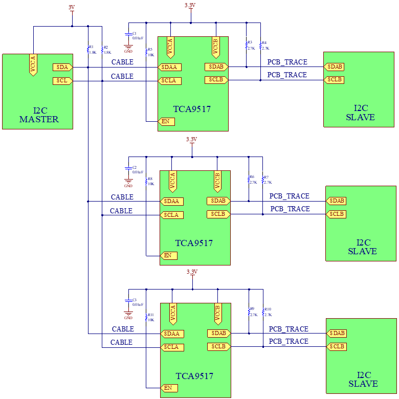
I noticed 2 design flaws in the diagram above:
- The VCCA is not connected to the A-side supply voltage, VCCA and VCCB are connected to the B-side supply voltage instead. The TCA9517DGKRQ1 chip should work as a voltage-level translator, but the VCCA supply is not connected to the chip.
- There is only one decoupling capacitor placed close to the VCCA side.
Can you help to understand how this incorrect configuration in the I2C bus repeater will affect the I2C communication?
The system has multiple I2C errors. To take care of some of the I2C errors, the firmware implements retries to resend the I2C packets after I2C errors. There are also I2C bus lockups when the SDA line is being held low by the I2C Slave. These type of I2C errors are catastrophic and the system cannot recover without a power cycle.
I noticed that unusual fast transitions in the I2C signal become the trigger for the I2C errors because impacts on the ability of the I2C decoders to understand the data on the line. I noticed that unusual fast transitions in the I2C signal become the trigger for 2C errors because affect the I2C decoder’s ability to decode the data on the line correctly. I’m using an I2C Bus analyzer and an oscilloscope with I2C protocol built-in plugged to the A-side to analyze and log the I2C frames.

Instead of getting a solid HIGH in SDA, there are fast transitions from HIGH to LOW and go back to HIGH. The I2C decoder in the oscilloscope stop decoding after 3 data bytes in this particular case. Check a zoom view in the picture below to get more details into the unusual fast transitions of the SDA line.

The only issues that I could find in the schematic is the ones that I pointed out (VCCA not connected to the A-side supply and not decoupling capacitor at B-side); can you please provide an insight of how could possibly affect the I2C signal this incorrect connection to the I2C bus repeater?
I also calculated the pullups min and max values, and they are in range, but I just wondering if the pullups are not strong enough. Any recommendation?
Is there any other issue in the diagram that standout?
Thank for your help,
EE Yandrie Oyarzabal

