This thread has been locked.

If you have a related question, please click the "Ask a related question" button in the top right corner. The newly created question will be automatically linked to this question.

PCA9535: Driving Optocoupler

Part Number: PCA9535
Other Parts Discussed in Thread: TCA9535, , TCA9555, PCA9555

Hello,

I am planning to use this device to drive an optocoupler (PN 140817143200). I am planning to drive it with a 12.5mA, so the total current of the octal will be within 100mA limit

For the Vcc I will use 5V. The questions are as follows:

1. Are there any issues Using Pn to drive optocoupler?

2. When I am going to set Pn pin Low, do I expect to see around 0.11V on the Pn pin according to the Figure 6-8 from datasheet at 12.5mA?

3. Is it a good practice to keep this 100k resistor across the optocoupler to reduce power consumption?

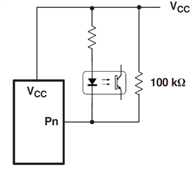
Here is an image of the driving principle

Best regards,

Timur

  • Timur,

    Thanks for reaching out! I heavily recommend the TCA9535 over the PCA9535 for new designs. The TCA9535 is the newer and more cost-effective version of the device. My answers below will apply to both devices, but I'll only refer to the TCA.

    1. Are there any issues Using Pn to drive optocoupler?

    Yes, you can use a P-port on this device to drive an optocoupler like the 140817143200. Regarding the 8 devices at 12.5 mA each, this looks good to me. Just be sure to account for device variations when designing, i.e. ensure that even in worst-case based on the 140817143200's max/min values, you'll still stay within the spec of the TCA9535.

    2. When I am going to set Pn pin Low, do I expect to see around 0.11V on the Pn pin according to the Figure 6-8 from datasheet at 12.5mA?

    While your number is accurate, I'd point out it is a bit too precise. Note that all devices have tolerances for specs, including here. This is test data from our devices, and you can see that there is variance across temperature. So I'd say you can expect to see it somewhere around there. The newer TCA9535 has a marginally lower VOL for the same sink current (see Figure 8 in that data sheet).

    3. Is it a good practice to keep this 100k resistor across the optocoupler to reduce power consumption?

    If you'd like to reduce the number of components on your board, I'd recommend looking at the TCA9555. This is identical to the TCA9535 except that the TCA9555 has an internal 100 kΩ pull-up resistor on the P-ports (and same for PCA9555 vs PCA9535).

    Best,

    Danny

    Edit: replaced functional diagram images (inadvertently uploaded wrong diagrams initially)

  • Hello Danny,

    Thank you for your reply, I have place the TCA9535 as an alternative, but it is out of stock everywhere and I need something to start with, therefore I have chosen PCA9535

    3. Is it a good practice to keep this 100k resistor across the optocoupler to reduce power consumption?

    If you'd like to reduce the number of components on your board, I'd recommend looking at the TCA9555. This is identical to the TCA9535 except that the TCA9555 has an internal 100 kΩ pull-up resistor on the P-ports (and same for PCA9555 vs PCA9535).

    For TCA9555 it is the same story as for TCA9535, i.e., it is out of stock everywhere and for the PCA9555 for the required package it seems that there is not enough stock (because I want to interchange it to TCA version and PCA and TCA, but TCA does not support all packages that PCA does)

    1. So if I will be using PCA9535/TCA9535, do I need to put a 100k resistor across the optocoupler?

    2. I have another question which came across. For the I2C signal do the SCL and SDA signal need to be the same voltage as Vdd, as our I2C master controller has a 3.3V for the I2C signal, so can we use this 3.3V voltage for the I2C signal?

    Best regards,

    Timur

  • 1. The 100 kΩ is needed only if the pin is configured as an input. When you output a high voltage, no extra resistor is needed.

    2. The I²C switching threshold depends on VCC. So you have to run the PCA9535 at 3.3 V. (It should be no problem to adjust the optocoupler resistor for that.)

  • Thanks for getting this information

    What would be a default state of outputs, when Vcc only applied and there is no I2C signal?

  • As shown in table 8-3, the default output state is high. But this does not matter because the default configuration for all pins is input (i.e., high impedance, and no current flows).

  • 1. The 100 kΩ is needed only if the pin is configured as an input. When you output a high voltage, no extra resistor is needed.

    I got confused, you have said that 100k is needed if pin is configured as input, and on the next message you have said default configuration for all pins is input. So do I need to put 100k or not?

    Thanks

  • If the pin is an input only a short time during power up, it does not matter.

  • Thank you

    Do I need to leave open unused pins then? 

  • Inputs must not float. So unused pins should get a pull-up resistor, or be configured as outputs.

  • Would pull-down work as well?

  • Yes; the only thing that matters is that the input does not float.