This thread has been locked.

If you have a related question, please click the "Ask a related question" button in the top right corner. The newly created question will be automatically linked to this question.

TCAN1044A-Q1: Power dissipation of Transceiver, RT and CM selection

Part Number: TCAN1044A-Q1

Hello TI team,

I have following questions on TCAN1044A-Q1, terminal resistor and CM choke:

1. The power dissipation of  TCAN1044A-Q1 transceiver is calculated as:

Pd = [(1-D) * Icc_rec * Vcc + D * Icc_dom * (Vcc-Vo_dom) + Vcc*Iq]

considering D = 0.5 for 50% in dominant and 50* in recessive mode. 

Please confirm whether above is correct way to calculate it.

2. What is the max supply avg current I should consider for TCAN1044?

   If I consider D = 0.5, can i calculate the avg supply current as follows:

I.avg = [D * (Icc_dom + Icc_rec) + Iq] , pls confirm

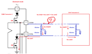
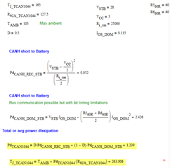
3. For termination resistance power dissipation; when CANH = Vbat ; CANL = GND

    Can I calculate power dissipation of Rterm as follows:

Pd(RT)  = (I.sc_CAN/2)^2  * RT * D

OR  D * (I.sc_dom/2)^2  * RT + (1-D) * (I.sc_rec/2)^2  * RT

4. For CM choke selection, I have read many app notes which say CM choke is last stage option if emission tests cause an issue although to keep a place holder and select component, I need following information:

Current rating:  I can probably use Icc_dom and Icc_rec to cover current rating of the choke, 

Inductance: Now to select a value which have minimum insertion loss for CM signals in specified range, that i got but not getting how to select the inductance value.

Regards,

Sunney

  • Hi Sunney,

    Your understanding here seems mostly correct. I will touch on a few things to make sure you are getting the full picture for these topics. 

    1. This is the correct way to calculate the average current requirements of the CAN circuit in a normal operating mode. However, this is not the power dissipation of the transceiver itself, but rather the whole CAN circuit including the termination resistance. Primarily, the dominant current will be driven through the termination resistor to create a bus differential. This means that most of the power and therefore heat will be dissipated by the resistors in this case. 

    2. Close here. The dominant and recessive currents need to be split up fully based on the value of D: I_avg = [D*I_dom + (1-D)*I_rec + Iq]. 

    3. This is a relatively complex topic, so I will leave a link to another thread that outlines this in detail. To be brief, most fault conditions that cause large currents through bus termination do not persist for very long, and those that do are unlikely enough to not be accommodated in most systems (i.e. CANH short to Vsup while CANL also shorted GND). Therefore the average power dissipation of termination resistors is expected to be much smaller than theoretical fault cases. Typical ratings I see for 12V systems are 0.5W for single termination or 0.25W for split termination. 
    https://e2e.ti.com/support/interface-group/interface/f/interface-forum/246035/wattage-requirements-for-can-bus-terminating-resistor-with-sn65hvd233?tisearch=e2e-sitesearch&keymatch=SN65HVD255 

    4. Similar story on CMC ratings as mentioned for termination ratings: we don't always account for the worst-possible fault case since they are so unlikely. So we can generally assume that bus currents will be limited around 100mA and rate the CMC current accordingly. Common inductance values are 51uH and 100uH. These work well for typical CAN data rates while providing effective common-mode filtering. 

    Let me know if you have any more questions.

    Regards,
    Eric Schott

  • Hi Eric thanks for the detailed response, it helped to better understand the analysis.

    Although I am little confused about one case of dominant state.

    When CAN Transceiver 1 is in transmit mode and state is Dominant, assume STB event happened on CAN_H. This case will have Rbus connected between VBAT and close to ground voltage (~1.5V) and I.sc.can will come into the picture.(I guess untill the timeout by master)

    Questions are:

    1.  CAN Transceiver 2, when in Receive mode will have both HS and LS drivers ON?

    2. If yes, during short to BAT on CAN_H in dominant state, both the CAN transceivers will have their limit on ISC.CAN and total

    ISC.CAN.TOTAL = ISC.CAN1 + ISC.CAN2 will be drawn from V.BAT which will imply that ISC.CAN.TOTAL/2 will flow from RBUS1 and RBUS2, which is approximately ISC.CAN of one transceiver.

    Note: if there will be other nodes, assumption is those will be in high impedance state and Req ~ Rbus1 || Rbus2.

    Is above understanding correct?

    Power dissipation of Rbus:

    Pd.Rbus = D*Pd.rec + (1-D)*Pd.dom

    Regards,

    Sunney

  • Hi Sunney,

    You make an excellent point here. When multiple transceivers are driving a dominant state simultaneously (such as during an error frame), the cumulative current limits could cause a larger current to flow through the termination resistors. This would result in a peak power through the resistor proportional to the battery-voltage of the fault and the full current across the resistors. However, the time that the system remains in this state will limit the amount of energy that the resistors themselves need to dissipate. The main thing to look at in this case is the dominant fault time of the system before the CAN transceiver stop driving the dominant state. 

    The maximum time that any CAN bus will remain dominant is 11 bit-times (five successful dominant bits followed by an error frame). It is during this time that the bus fault will be causing the maximum fault current to pass through the termination resistors. This time is limited by the dominant timeout of the transceiver (~4ms) which also dictates the minimum data rate of the device (~10kbps). However, most systems will operate at more reasonable CAN speeds of several hundred kbps. We'll use 100kbps as an example of a relatively slow rate and thusly a long fault time. 11 bit-times of a 100kbps signal results in a dominant fault time of 110us. During this time, the full fault current will flow through the termination resistors and heat them up. However, because this is such a short amount of time, it is unlikely in most fault cases that this heating will be more than a couple of degrees celcius - not enough to cause damage to the resistor. 

    Do to this limited dominant fault time provided by the CAN protocol, the average power dissipation required by the termination resistors is much less than the potential power that can be provided by a single bus fault. This allows for smaller and more readily available resistors to be used in CAN systems without risk of damage from most bus faults. 

    Let me know if this explanation is clear or if there's another question I can address. 

    Regards,
    Eric Schott

  • Hi Eric, the above explanation is clear in case of termination resistor power dissipation, thank you. As in case of resistor, I can refer Single pulse graph for the calculated duration based on baud rate and can get the maximum power dissipation allowed. 

    Now for CAN transceiver same thing will happen when the CAN bus will remain dominant due to fault and 11bits time is in my case comes around 44us (for 250KHz).

    For this time duration, CAN transceiver will dissipate around 2W. Is there any supporting data for short duration peak power in case of CAN transceiver, that will help to defend the calculation.

    Calculation

    Regards,

    Sunney

  • Hi Sunney,

    Each CAN transceiver will limit the amount of current through the CAN driver and thus will not need to handle the full possible current of the short. Each transceiver is also equipped with a thermal shutdown feature that will automatically disable the driver if the device gets too hot to prevent damage. 

    Regards,
    Eric Schott

  • ok Thank you Eric for your support

    Regards,

    Sunney