Part Number: DP83867ERGZ-S-EVM
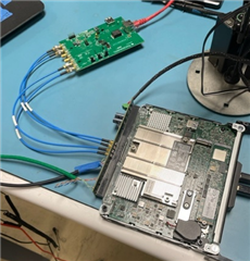
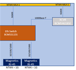
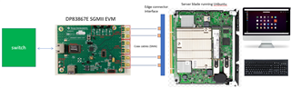
I have been struggling to get an EVM to make a connection between a server blade w/SGMII interface to a network switch connected to the RJ-45 port. My current test setup is very basic and I thought it should have worked essentially out of the box. Below is an image of the setup. The server is running a version of Ubuntu. For my basic test, I am launching the browser and trying to ping some IP addresses through the switch. This area is not my normal field of expertise and I am having to learn a lot. I also know that there is likely a myriad of things that could be causing the problem but I wanted to start off this thread with basic info and solicit ideas for checking some basics first.
First, this exact configuration works fine if I replace the TI EVM board with a demo board from another mfr (Marvel 88X3540) but that part is way to much of an overkill for this application.
Second, I'm not yet setup to check register values since my MSP430 launchpad has not arrived yet to use the USB2MDIO GUI.
The straps are default except for:
LED_2 changed to Mode 1 (removed both Rhi and Rlo). I assume that I don't have to worry about RGMII clock skew settings.
LED_1 changed to Mode 1 (removed both Rhi and Rlo) I assume that I don't have to worry about RGMII clock skew settings.
LED_0 set to Mode 4. (jumper at 2-3 and R6 = 2.49K).
Interestingly, when I first checked the status of the straps using a basic DMM on the LED_x pins with the RESET button pressed, a couple of the V DC values didn't make any sense according to table 4 in the datasheet. For example, with LED_0 jumper set for 2-3 (mode 4), the DMM reported 1.1V (range should be 1.73-2.22V). This was on two different EVM boards. After probing more and removing/swapping resistors, I found out that R6 had an 11K resistor instead of a 2.49K (cause for 1.1V reading). When I installed a real 2.49K resister, the reading is now 1.95V. Could this have damaged anything in the chip?
I checked the strap on RX_CTRL pin (with DMM) and it looks OK for mode 3 @ 0.607V
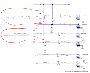
Even though I don't need to set a PHY ADDR to anything other than 0000, and the straps on RX_D0 and RX_D2 were not populated on the EVM, I saw the not below Table 4 that recommended they be populated with specific values when using SGMII Mode 4. So, I tried that too but to no apparent effect.
In the image below (my basic setup), the SGMII signals connect with ~ 10" SMA coax cables. I don't need the clock output so I left that unconnected.
When I connect the CAT5/6 cable to the switch, I get LINK and 1000B-T LEDs coming on. I also get Activity LED flashing as expected. Any thoughts on what else I can look for/check from a hardware or setting perspective before my Launchpad arrives?
Thanks,
Phil