This thread has been locked.

If you have a related question, please click the "Ask a related question" button in the top right corner. The newly created question will be automatically linked to this question.

SN65HVD3082E: RX issue between two devices

Part Number: SN65HVD3082E

Hello there!

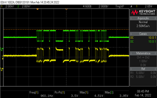
I have a device that uses SN65HVD3082ED as a RS485 transceiver to exchange data with my product, which sometimes uses transceivers from others companies (like MAX485). My product acts like a controller and the device as a peripheral, there's no other device on the same line. The problem is, the device receives a data request correctly, but my product don't receive the response (or any data). Using some cheap RS485-to-USB converter, the communication between PC and the device is flawless. Also my product is working fine, because it communicate with several third party devices without any problem! So I'm totally lost of what's going on... The picture below shows "inside" both hardwares:

Does anyone know what's going on here?

Thanks a lot!

  • Why are R4/R5 so high? And where is the termination resistor on the peripheral side?

    Can you show an oscilloscope trace?

  • Hi Clemens!

    That's the point! The peripheral device was developed by another company and they don't want to cooperate in a solution (it was very hard to get from them the RS485 circuit!).

  • That peripheral definitely does violate the RS-485 specification. But R1/R3 in your controller might be too strong.

    I'd guess that the RS485-to-USB converter works because R1/R2/R3 have higher values.

    Can you show an oscilloscope trace?

  • Hi Clemens!

    Please, take a look at the picture below:

    Green is for "A" and yellow for "B".

  • Hi Pedro,

    Is there anyway to add a termination to the peripheral side? This could be an issue in receiving the data as Clemens alluded to. Also can you modify R1/R3 weaken their pull strength as that difference could be causing issues on the bus as well. 

    What cheap USB to RS-485 converter are you using - if you can share that would be great!

    Also for the scope shot provided - what side is signal taken at the controller or peripheral - could I possibly get both images - because besides termination R4/R5 are also very high which could be causing attenuation. 

    Also if possible scope shots from the cheap USB converter too would be helpful as comparing that to the working model may give some more clues what is happening - if there are more problems than just the peripheral connection device and/or strength of pull-ups/pull-downs on the controller side.

    Please let me know!

    Best,

    Parker Dodson

  • Hi Parker!

    I know it sounds impossible, but I'm trying to find a solution without changing both circuit... From peripheral side, the device is sealed (IP65 protection) and I'm pushing hard the company to fix this circuit (according the specification) but no success yet. From controller side (my side), I can try to change R1/R3 to 470R, I think it's the same value from the USB converter. The problem is, my device is in production for a long time, it's really hard to replace them on field. That's why I was thinking about some kind of "adapter" between both device.

    Regarding the USB to RS-485 converter, this is the one: www.aliexpress.com/.../32285139690.html

    About the scope shot, it's between R2 points.

    Thanks a lot!

  • That waveform looks OK. Is it from the controller to the peripheral?

    To make R1/R3 weaker, increase their value. With R6/R7 in the circuit, you should not need them at all.

  • Hi Pedro,

    I apologize for the delay! I didn't see this notification for your response to this thread - once again I deeply apologize!

    So essentially it isn't possible to fix this without changing the circuit. The pull-up / pull-downs on the controller side alone are not needed as the peripheral already has a set - generally this only needs to be on one side of the bus, and if added to more than 1 spot on the bus the values need to be increased for proper functionality. 

    Next - if the cable isn't very long relative to the rate (essentially being able to neglect things like reflections as the signal path isn't long enough relative to signal wavelength ) then a higher termination resistance or - just none at all would overcome the high series resistance on the peripheral and data could be exchanged. There is still a big "if" with this setup as it is very dependent on the signal path length between controller and peripheral. 

    This isn't the simplest solution but that is the best course of action if the peripheral cannot be updated - I understand its hard for the controller as well, but this current setup is more or less expected based on resistances of the signal pathways + voltage drops  on the driver itself - those series resistances very much are the largest degradation of performance on this application + no termination resistors on peripheral. 

    Please let me know if you have any other questions!

    Best,

    Parker Dodson