This thread has been locked.

If you have a related question, please click the "Ask a related question" button in the top right corner. The newly created question will be automatically linked to this question.

TIC10024-Q1: Wetting current setting and Polling time

Part Number: TIC10024-Q1
Other Parts Discussed in Thread: TIC12400-Q1,

Hi team,

I have a question about the configuration of the TIC10024-Q1(or TIC12400-Q1). 

1. Wetting current. 

I want to control the wetting current strictly between min 5mA max 10mA, but there is only 5mA or 10mA setting which violate 

min 5mA and max 10mA respectively due to its tolerance. 

Is there any way to control the wetting current between 5mA to 10mA? 

Is it possible to combine 2 (2mA + 5mA) or 3 (2mA x3) INx pins together to increase wetting current?

Or is there any other way using external circuit? 

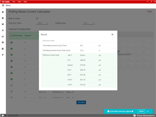
2. Polling time and continuous mode. 

Is it possible to combine Polling mode and continuous mode in one device?

For example, IN0 to IN7 is polling mode, IN8 to IN23 is continuous mode?

I would like to minimize current consumption and use polling mode for 6 inputs, but other pins need to detect 

switch status in <1ms interval. Because the minimum polling time setting is 2ms, these pins need to read continuous mode.

3. Polling time selection.

3-1. Is there a way to select polling time by Input pins or one polling time setting applies to all input pins?

3-2. Is there a way to configure polling time which is not listed in the register? For example 5ms, 10ms?

regards,

regards,

  • 4. Could you advise how much is the maximum current calculated by EVM GUI tool below?

    +10% from typical value below is enough?

    5. tpoll_act_time and Resd, Cesd

    Could you advise how to consider time constant of Resd, Cesd to select tpoll_act_timing?

    I concern if INx pin voltage get stable before sampling. 

    regards,

  • Tsuji-san,

    This should work assuming you are using either only current sources or only current sinks.

    Polling vs. continuous mode is a single mode for the device. Unfortunately it is not individually selectable for each pin. Note that the maximum sample frequency in either mode is 2 ms. This device won't be able to achieve 1 ms detection timing in either mode.

    The same idea applies to the polling time. It is a uniform time for each of the pins. POLL_TIME can be set to 4 ms or 8 ms per your design requirement, but all of the settings are listed in the register map, no secret ones.

    For your current estimation question, the GUI calculator basically sums up the typical current in polling mode across all of the inputs during an entire polling cycle. It doesn't take into account factors that arise due to external components. Your worst case for ambient could be a lot higher and is difficult to characterize easily, particularly at higher temperatures.

    The question about the RC time constant is a good one. This is not exactly the same as an ideal discharge curve because of the current source from the TIC12400-Q1. Also, given the setup shown in Figure 10-1 of the data sheet, discharge should be quick. The RC discharge from CESD would be across SW (not RESD). There would, however, be a DC current across the resistor producing V ≈ IPOLL*RESD. I would check the characteristics of the mechanical switch itself to help with this design process.

    Best,

    Danny

  • Note that I've updated the prior response to correct a few errors Slight smile