This thread has been locked.

If you have a related question, please click the "Ask a related question" button in the top right corner. The newly created question will be automatically linked to this question.

TCAN1057A-Q1: CAN waveform have a strange... level shift?

Part Number: TCAN1057A-Q1

Hello ...

       We used TCAN1057ADDFEQ1 for our system design...

       and you find the attached of the Sch...

       we measured the system initial of the CAN waveform...(system initial  means system power ON)

      and you can see the waveform as attached picture...
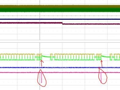
      yellow : CAN+

      green :CAN-

      Blue: system power supply

     Red:TX_CAN

     you can see that CAN+/CAN- has some "overshoot" likes some offset? when TX_CAN have send data...(red mark and red arrow mark)

     We checked many times, the same as CAN+/CAN- suddenly drift up (How to say in English, sorry... likes up and then down) then recover to normal when TX_CAN send data every time...

      and then the customer asked me why has this phenomenon...

     ★measure setup :   when the system is not powered on, the CAN analyzer is used to send CAN messages with a cycle of 100ms. 

      the system and  CAN analyzer have 120ohm resistor(because the system has no mounted as a red dotted lines in circuit)

     so could you please explain it why in detail?

Thanks

B,R

hejun

  • Was there any other device connected to the bus?

    The ACK bit at the end of each packet is driven not by the transmitter but by all devices that have correctly received the packet, so it is normal that its voltage is different.

  • Thanks Clemens!

    Hi Hejun,

    This is fairly common in systems with longer cables that may experience some ground shift between nodes and have larger bus capacitance due to longer cables. What we see in the scope shots is the common-mode voltage settling after being driven by a remote node for the ACK bit. Because the average voltage on CANH and CANL is higher during this time, the common-mode voltage of the bus shifts up during the dominant state. This happens quickly because this state is being actively driven by the remote node. When the bus transitions back into a recessive state, it settles to the nominal recessive level by discharging through the various recessive biases provided by all the transceivers. Because this bias is weak relative to the driven dominant state, it takes longer and is visible at the end of the CAN frame or anytime when two nodes hand-off communication. 

    This behavior is unlikely to impact data integrity because only the common-mode of the bus is impacted, thus the differential signal that contains the data is not affected. Because the system experiences some shift in the common-mode, this does marginally impact emissions, but the change is relatively small and infrequent, so this will only be significant for very sensitive systems. 

    Let me know if you have any more questions.

    Regards,
    Eric Schott