This thread has been locked.

If you have a related question, please click the "Ask a related question" button in the top right corner. The newly created question will be automatically linked to this question.

SN65DSI84: Intermittent Issue of no Display

Part Number: SN65DSI84

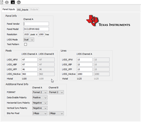
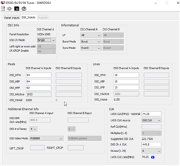
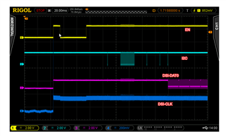
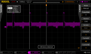
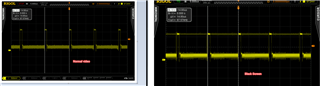
We have an intermittent issue, where we do not get any display output on the screen, even though the SNDSI84 has been correctly initialized. we have followed the initialization sequence precisely, as indicated by the attached waveform for during initialization. In our case the clock source for the  SN65DSI84 is the DSI clock. Therefore, the DSI clock is in High speed (HS) continuous mode.

We follow all the sequence of detecting error (after certain wait period of DSI HS enabled) and re-initialization upon error detection. However, there are cases where there is no display, but the register 0xE5 returns 0, indicating no error.

we are at a loss what could be causing this behavior, any help will be highly appreciated.

  • Hi,

    I will point you to this FAQ on debugging the flicking issue seen with the DSI83/84/85, https://e2e.ti.com/support/interface-group/interface/f/interface-forum/990480/faq-sn65dsi84-how-to-debug-flickering-video-with-sn65dsi83-sn65dsi84-and-sn65dsi85.

    Does color bar work correctly in this case?

    If the color bar works, then can you measure the HSYNC and make sure the HSYNC frequency from the DSI side matches with the LVDS panel requirement?

    Thanks

    David

  • Hi David.

    The colors all look correct.

    we measured the hsync to hsync timing on DSI and it is as expected (14 us as shown in the DSI tool).

  • Hi,

    Can you share the LVDS panel spec? 

    Are you able to get any display output on the screen? Does the scope captured waveform show the working or non-working case?

    Can you also check and if the format (1 or 2) is correct?

    Thanks

    David 

  • DV215FHM-NN0.pdf

    Hi,

    I've attached the datasheet for the display.

    we get the output on the screen about 95% of the time. Its the elusive 5% of the time that we get the black screen.

    The waveforms were captured during the working scenario.

    on the Format-1 or Format-2, the display datasheet is not clear on which format it uses, hence we used the default 24bpp, format 2

  • Hi,

    Looking at the datasheet, the panel supports 24-bit, format 2. 

    If you switch to the test bar, does it work 100% of time? 

    Is it possible to capture HSYNC during the non-working case?

    Thanks
    David

  • Hi.

    Yes the test pattern works 100% of the time. When we write the registers to display the test pattern during non-working condition (black screen) the display comes back alive with the test pattern.

    I write following values

    0x20 0xc0
    0x21 0x03
    0x3C 0x10

    However inquiring register 0xe5 during these black screens still returns 0x00. (we have queried this register several times manually so the wait time of 5 ms is well surpassed)

    For the measurement of Hsync, would you like us to measure the timing hsync-hsync during the black screen as well  or just the nature of the waveform. Our confusion is, the error register is reporting 0x00 so its essentially seeing a perfect hsync and other parameters right?.

  • Hi,

    With the test pattern working correctly 100%, it points to the fact that the LVDS output is working correctly. 

    I would agree that you should see some error status bits at register 0xE5 being set if there are any error conditions on the DSI input side. I want to check the  timing of HSYNC-HSYNC during the black screen to make sure the DSI source is still sending the correct HSYNC timing. 

    Do you have a way to use a reference clock instead the DSI clock? This is to double check and make sure the DIS clock itself is not the root cause of the problem.

    Thanks

    David 

  • we have an external 48MHz crystal going into the chip which we are currently not using. I will go through the DSI tool to create the correct LVDS clock (74.25) using this crystal. I will report back my findings.

    Update !!

    The DSI tool, for some reason doesn't show the calculate button anymore.

    I was planning to use 48*3/2 to create the 72 MHz LVDS clock,  as the 74.25 MHz cannot be accurately generated from 48 MHz.

    However, the divisor is greyed out and unelectable.

    The calculate button is gone, and I can't re-size the dsi tool. I unstalled and re-installed at no avail.

  • Update 2:

    I manually changed the registers to use the 48MHz reference clock. Modified 0x0A and 0x0B. Same results.

    Also tried changing the register 0x11 for channel equalization. Same results.

    Update 3

    I measured HSYNC at the DSI during normal operation and during black screen. I see the same exact waveforms during the working vs not working scenarios.

    On a closer look at the errors, we see that whenever the video is good, error register is always 0x80. however, whenever there is black screen it returns error as 0x00.

    During good video, after clearing the 0xE5 register immediately goes to 0x80. But during black screen it stays 0x00. Its as if no error is bad for black screen.

  • Hi,

    The divisor is only selectable when DSI_CLK is selected as the clock input source. So it is expected to grey out when reference clock is selected. I attached my version of DSI Tuner SW, can you check and see if it works?

    0143.DSI Tuner 2.1.zip

    Looking at the HSYNC waveform during the black screen, it looks like you are putting the scope in persistence mode and thee is a time when HSYNC behavior changes, it went from an active high signal to an active low, can you double confirm this?

    Thanks

    David

  • Hi,

    I measured the waveforms again today and can confirm that they are identical. It's the fact that I'd paused the oscilloscope during the first measurement while it was freely running on the second instance, it looks different on the screenshot I shared

    The clocks look identical on both occasions as well. 

    Reading off the entire registers on the chip on both good and bad instances show identical values.

    The incoming waveform are identical as well...

    good video

    addr 0x00 0x01 0x02 0x03 0x04 0x05 0x06 0x07 0x08 0x09 0x0a 0x0b 0x0c 0x0d 0x0e 0x0f
    0x00: 0x35 0x38 0x49 0x53 0x44 0x20 0x20 0x20 0x01 0x00 0x85 0x28 0x00 0x01 0x00 0x00
    0x10: 0x26 0x00 0x59 0x00 0x00 0x00 0x00 0x00 0x6C 0x00 0x03 0x00 0x00 0x00 0x00 0x00
    0x20: 0x80 0x07 0x00 0x00 0x38 0x04 0x00 0x00 0xE1 0x03 0x00 0x00 0x14 0x00 0x00 0x00
    0x30: 0x03 0x00 0x00 0x00 0x3C 0x00 0x04 0x00 0x78 0x00 0x26 0x00 0x00 0x00 0x00 0x00
    0x40: 0x00 0x00 0x00 0x00 0x00 0x00 0x00 0x00 0x00 0x00 0x00 0x00 0x00 0x00 0x00 0x00
    0x50: 0x00 0x00 0x00 0x00 0x00 0x00 0x00 0x00 0x00 0x00 0x00 0x00 0x00 0x00 0x00 0x00
    0x60: 0x00 0x00 0x00 0x00 0x00 0x00 0x00 0x00 0x00 0x00 0x00 0x00 0x00 0x00 0x00 0x00
    0x70: 0x00 0x00 0x00 0x00 0x00 0x00 0x00 0x00 0x00 0x00 0x00 0x00 0x00 0x00 0x00 0x00
    0x80: 0x00 0x00 0x00 0x00 0x00 0x00 0x00 0x00 0x00 0x00 0x00 0x00 0x00 0x00 0x00 0x00
    0x90: 0x00 0x00 0x00 0x00 0x00 0x00 0x00 0x00 0x00 0x00 0x00 0x00 0x00 0x00 0x00 0x00
    0xa0: 0x00 0x00 0x00 0x00 0x00 0x00 0x00 0x00 0x00 0x00 0x00 0x00 0x00 0x00 0x00 0x00
    0xb0: 0x00 0x00 0x00 0x00 0x00 0x00 0x00 0x00 0x00 0x00 0x00 0x00 0x00 0x00 0x00 0x00
    0xc0: 0x00 0x00 0x00 0x00 0x00 0x00 0x00 0x00 0x00 0x00 0x00 0x00 0x00 0x00 0x00 0x00
    0xd0: 0x00 0x00 0x00 0x00 0x00 0x00 0x00 0x00 0x00 0x00 0x00 0x00 0x00 0x00 0x00 0x00
    0xe0: 0x01 0x7D 0x00 0x00 0x00 0x80 0x00 0x00 0x00 0x00 0x00 0x00 0x00 0x00 0x00 0x00
    0xf0: 0x00 0x00 0x00 0x00 0x40 0x00 0x00 0x80 0x00 0x00 0x00 0x00 0x00 0x00 0x00 0x00


    Black screen
    addr 0x00 0x01 0x02 0x03 0x04 0x05 0x06 0x07 0x08 0x09 0x0a 0x0b 0x0c 0x0d 0x0e 0x0f
    0x00: 0x35 0x38 0x49 0x53 0x44 0x20 0x20 0x20 0x01 0x00 0x85 0x28 0x00 0x01 0x00 0x00
    0x10: 0x26 0x00 0x59 0x00 0x00 0x00 0x00 0x00 0x6C 0x00 0x03 0x00 0x00 0x00 0x00 0x00
    0x20: 0x80 0x07 0x00 0x00 0x38 0x04 0x00 0x00 0xE1 0x03 0x00 0x00 0x14 0x00 0x00 0x00
    0x30: 0x03 0x00 0x00 0x00 0x3C 0x00 0x04 0x00 0x78 0x00 0x26 0x00 0x00 0x00 0x00 0x00
    0x40: 0x00 0x00 0x00 0x00 0x00 0x00 0x00 0x00 0x00 0x00 0x00 0x00 0x00 0x00 0x00 0x00
    0x50: 0x00 0x00 0x00 0x00 0x00 0x00 0x00 0x00 0x00 0x00 0x00 0x00 0x00 0x00 0x00 0x00
    0x60: 0x00 0x00 0x00 0x00 0x00 0x00 0x00 0x00 0x00 0x00 0x00 0x00 0x00 0x00 0x00 0x00
    0x70: 0x00 0x00 0x00 0x00 0x00 0x00 0x00 0x00 0x00 0x00 0x00 0x00 0x00 0x00 0x00 0x00
    0x80: 0x00 0x00 0x00 0x00 0x00 0x00 0x00 0x00 0x00 0x00 0x00 0x00 0x00 0x00 0x00 0x00
    0x90: 0x00 0x00 0x00 0x00 0x00 0x00 0x00 0x00 0x00 0x00 0x00 0x00 0x00 0x00 0x00 0x00
    0xa0: 0x00 0x00 0x00 0x00 0x00 0x00 0x00 0x00 0x00 0x00 0x00 0x00 0x00 0x00 0x00 0x00
    0xb0: 0x00 0x00 0x00 0x00 0x00 0x00 0x00 0x00 0x00 0x00 0x00 0x00 0x00 0x00 0x00 0x00
    0xc0: 0x00 0x00 0x00 0x00 0x00 0x00 0x00 0x00 0x00 0x00 0x00 0x00 0x00 0x00 0x00 0x00
    0xd0: 0x00 0x00 0x00 0x00 0x00 0x00 0x00 0x00 0x00 0x00 0x00 0x00 0x00 0x00 0x00 0x00
    0xe0: 0x01 0x7D 0x00 0x00 0x00 0x80 0x00 0x00 0x00 0x00 0x00 0x00 0x00 0x00 0x00 0x00
    0xf0: 0x00 0x00 0x00 0x00 0x40 0x00 0x00 0x80 0x00 0x00 0x00 0x00 0x00 0x00 0x00 0x00

  • Hi,

    Can you change register 0x28 to 0x21 and register 0x29 to 0x00 to see if it helps?

    Thanks

    David

  • Changing those registers had the same results. Still getting black screens ocassionally and error reported as 0x00 or 0x80

  • Hi,

    Can you please share a screenshot of the DSI84 initialization similar to the image below?

    ...

    Also, if you toggle PLL_EN or RESET during the blanking screen, does the screen return back to normal?

    Thanks

    David