This thread has been locked.

If you have a related question, please click the "Ask a related question" button in the top right corner. The newly created question will be automatically linked to this question.

DS90UB954-Q1: hot plug detection

Part Number: DS90UB954-Q1

Hi,

I found the previous discuss that hot plug is supported.

I'm using 954/953 currently and will swicth to 936/935 later.

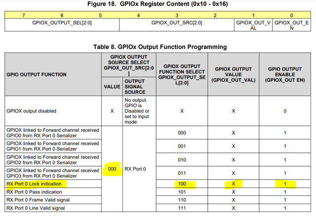
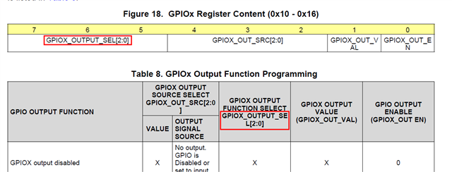
 I tested that when I remove/insert the coaxial cable, the GPIO3/INTB pin don't send signal. The 954 GPIO3 register setting is:

reg 0xf=0x70

reg 0x13=0xd1

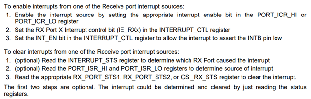
Is there a way to aware that the cable is removed/inserted?

Thanks.

  • Hello Chris,

    In general, the UB954 is not designed to support hot plugging operations. Our FPD-Link devices were designed to be used in systems where the SER and DES are always connected. But there are some ways to implement this through software intervention.

    Also, please keep in mind that if you are removing/inserting the cable while the FPD-Link devices are active, then there may be some ESD events that could damage our devices. Please consider adding ESD protection along the FPD-Link traces (DOUT+/- and RIN+/-).

    1) One method is to monitor the LOCK pin and PASS pin. Or enable interrupts on the LOCK or PASS registers (see register 0xD9 in the UB954 datasheet). Once the cable is removed, LOCK will naturally be lost and an interrupt can be triggered on the change in LOCK status.

    2) Another method is through GPIOs, where register 0x0F selects which GPIO pins are inputs/outputs and register 0x13 selects the output source for GPIO3.

    a) reg 0x0F = 0x70   // GPIO0-3 input are disabled

    b) reg 0x13 = 0xD1   // Reserved?

    The setting for reg 0x13 does not seem valid. Please refer to Table 8 in the UB954 datasheet to select the source of the GPIO3 output. For example, if reg 0x13 = 0x11, then GPIO3 will output the Rx Port 0 LOCK.

    If a cable is removed and the software detects it through GPIO, the following actions are recommended, in order to prevent MIPI faults that confuse the SoC:

    - If a camera/cable is disconnected, then detect loss of LOCK through GPIO and then disable the forwarding at the specific Rx port in reg 0x20 of the 954

    *Note that this still may cause an error in the SoC since the SoC may have received a partial frame from the camera by the time it was removed. We have no control of that from the FPD-Link side

    - Re-connect the camera/cable, wait for lock stable, restart AEQ by setting 954's register 0xD2[3]=1.

    With 5ms delay, enable this camera's forwarding by setting 0x20

    That should make things as deterministic as possible from the FPD-Link side.

    Best,

    Justin Phan

  • Hi Justin,

    Thanks for your quick reply.

    One thing to note, you seem misunderstanding the table 8, the bits order is by figure 18, so 0xd1 is not reserved, it's "Device interrupt active low".

  • Hello Chris,

    You are correct. I seem to have gotten mixed up for a second. If you set reg 0x13 = 0xD1, then your understanding is correct. However, since you wish to use GPIO3/INTB as the interrupt, then the instructions in section 7.5.8.2 FPD-Link III Receive Port Interrupts can be followed instead:

    1) First, select the Rx Port to write to in reg 0x4C. Then, perform the following.

    The IE bit that could be set in register 0xD9 is the IE_LOCK_STS bit. Once this interrupt is triggered, there are a number of registers that can be read, such as the CABLE_FAULT bit, to check for the error. See 7.4.11.3 RX Port Input Signal Detection in the datasheet for more details.

    Best,

    Justin Phan