This thread has been locked.

If you have a related question, please click the "Ask a related question" button in the top right corner. The newly created question will be automatically linked to this question.

TUSB522PEVM: 23, 22pin did not get any differential signal

Part Number: TUSB522PEVM
Other Parts Discussed in Thread: TUSB522P

We did an experiment today:

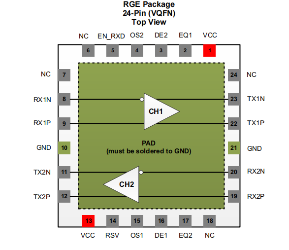
200mV differential signal was added to pins 8 and 9 (attempts were made in the frequency range of 1m ~ 20m). The signal was measured on pins 23 and 22, and no differential signal was obtained.

Similarly, it is useless to do the same experiment with 20, 19pin and 11, 12Pin.

Measured, the power supply is normal, EN_ RXD is high.

As above, please help confirm the reason?
  • Hi,

    TUSB522P has internal state machince for USB LFPS signaling that will prevent the driver from being fully active until the appropriate pattern is received. What are you trying to test here exactly?  

  • Hi,

    After reading the reply, that is to say, the differential channel of IC internal band protocol cannot pass through directly, right?

    We just want to test whether the differential channel of IC works normally. Because our product can't be debugged now, we can't be sure whether the layout is bad or the IC itself doesn't work. The measured voltage of IC related pin is normal. Our products are only USB2 0, usb3 The data of 0 is not connected. Now we don't know what good way to solve the problems we encounter.

  • Hi,

    The best method to debug this will be to use a USB analyzer to look at the traffic directly. Without a BERT with the right patterns it will be very difficult to manually activate the USB channel. In a functional test USB 3 device only enumerate as USB 2, is there any warning message that pops up (Windows OS)?

  • Hello!

    In the function test, USB 3 devices are only enumerated as USB 2, which will prompt that the device driver is abnormal.

    I use the regular usb3 0 wire has been connected to computers and equipment and can be connected normally. It can ensure that the computer and equipment are OK. We've also tried laptops and desktops. They all have the same problem.

  • Is it possible that this IC is not suitable for our design? Our schematic diagram is shown in the annex.

    The input and output of our products are type-C interfaces. The input of tusb522p is the female seat of type-C and the output is the male seat of type-c. Is there a more appropriate IC recommendation?

    In our PCB design, rx1 and rx2 of type-C mother base are connected together; TX1 and TX2 are connected together. Similarly, the male end of type-C is connected in this way.

  • Hi Depeng,

    Can you provide a block diagram of your application?  Is there a RX to TX swap handled by a cable?

    When you connect the board to a USB 3.0 port, are you able to see any LFPS signaling?

    Regards,

    JMMN

  • Hi Depeng,

    Any update here?