Hi Team,
1) Currently I am looking for information to create the smallest possible landpattern for the TLK2711-SP. As the chip comes with long leads I’m not sure what the landpattern should look like.
How far can/should we cut off the leads before forming (assuming that is needed) and soldering?
Where can I find instructions on how to form the leads?
Note that since the part will not be implemented on a flight model, we don’t have to obey any space standards regarding component placement and soldering. We try to aim for the smallest possible footprint due to limited board space. Although it’s a space grade device, our product will not be send to outer space.
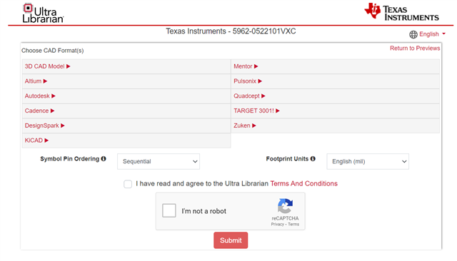
2) I tried to download the CAD symbol from the product folder, but it semm not to be available (anymore).
Thanks,
Alen