This thread has been locked.

If you have a related question, please click the "Ask a related question" button in the top right corner. The newly created question will be automatically linked to this question.

DS90UB948-Q1: Best Equalizer setting for DS90UB949 and DS90UB948

Part Number: DS90UB948-Q1
Other Parts Discussed in Thread: ALP

Hi Team,

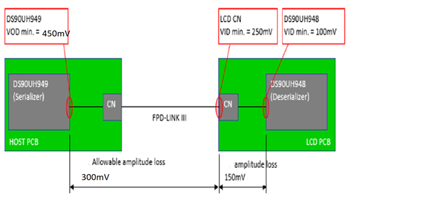
We have a loss in the Host side PCB + cable loss value is negligible approximate of 0B and Deserializer PCB loss of 5.2 dB. Totally we have a margin of 4dB to 5 dB between serializer and deserializer. 

We used dual port coax mode.  So consider the amplitude is 900mV /2 = 450mV transferred over the cable.

We would like to increase the gain of the de-serializer by enabling the AEQ. Please let me know the best setting for the equalizer.

DS90UB949A  - DS90UB948
Specifications Min Typ Max Unit
Vout from DS90UH949A 400.00 450.00 650.00 mV
Host Side PCB loss - 150mV 0.00 0.00 0.00 mV
Host Side PCB data 400.00 450.00 650.00 mV
Cable loss 0.00 0.00 0.00 mV
After cable 400.00 450.00 650.00 mV
Display side PCB loss 250.00 250.00 250.00 mV
Available Margin 4.08 5.11 8.30 dB


This is the sequence we followed AEQ enabling sequence:

  1. Ensure register 0x44 bit0 = 0 to enable AEQ.
  2. 0x35 bit 4 &5 should be 1 to enable a floor, set both=0 to set the floor to the minimum value.
  3. Set ADAPTIVE_EQ_FLOOR_VALUE in register 0x45, bits 3:0.  
  4. Re-initialize the AEQ by setting: 0x35 bit 6 - 1 then after some time 0 write – reinitialization
    1. data: 35h 30h
    2. data: 35h 70h
  5. Read the 0x3b for EQ1 and EQ2 to understand what the AEQ settings configured.

We adjusted to min to maximum value AEQ, but the gain is not increased at the deserializer side.

We added a 12dB attenuator in the cable to validate the AEQ gain.  we would like to increase the 4dB to 6dB gain on the receiver side. 

Thanks,

Selva S

  • Hi Selva,

    Let me look at the channel specs, and I will get back with you tomorrow or Monday.

    Aaron

  • Hi Aaron,

    Thank you, Looking forward to hear from you. selva 

  • Hi Selva,

    Sure. I will let you know if I find anything.

    Aaron

  • Hi Aaron,

    Do you have any update on this request?

    Thanks,

    selva

  • Hi Selva,

    Let me ping my team. I will get back with you.

    Aaron

  • Hi Selva,

    I reviewed your procedure how to tweak the EQ. I think step 1 and 2 in step 4 need to be swapped:

    1. Ensure register 0x44 bit0 = 0 to enable AEQ.
    2. 0x35 bit 4 &5 should be 1 to enable a floor, set both=0 to set the floor to the minimum value.
    3. Set ADAPTIVE_EQ_FLOOR_VALUE in register 0x45, bits 3:0.  
    4. Re-initialize the AEQ by setting: 0x35 bit 6 - 1 then after some time 0 write – reinitialization
      1. data: 35h 30h data: 35h 70h <- Restart AEQ
      2. data: 35h 70h data: 35h 30h <- Clear Restart
    5. Read the 0x3b for EQ1 and EQ2 to understand what the AEQ settings configured.

    Let me know if this helps.

    Aaron

  • Hi Aaron,

    Thanks for the data. Let me check with this update.

    1) I hope, if I set the floor value as a minimum, it will auto-increment based on the loss in the path and set the appropriate values once AEQ is active?

    2)  How does the ALP software alone show the strobe position? Is there any register to read the strobe position?

    Thanks,

    Selva S

  • Hi Selva,

    Let me investigate this, and I will get back with you.

    Aaron

  • Selva, 

    I have no idea what your goal is here but we do not recommend to manually adjust the equalizer and stobe settings like this. The devices are designed to automatically compensate the link and when you start doing these type of manual settings you are far more likely to break something in the long term vs. actually fixing the root of your issue. If you are having link problems I suggest to take a step back and do an evaluation of your channel s-parameters between SER/DES across frequency so that we can compare against the channel specs for the device RL/IL. Also I suggest to do a thorough evaluation of the HDMI clock jitter to make sure it is meeting the datasheet specifications and please disable any SSC from the HDMI clock to rule that out as well. 

    All this discussion on EQ setting and strobe is like a temporary bandaid to a larger issue and will cause more problems in the long run

    Best Regards,

    Casey

  • Hi Casey,

    thanks for the inputs.

    equalizer : 

    The manual equalizers adjustment just for debug purpose. As of now equalizer is not enabled.

    Clock : 

    we disabled the SSC.

    The clock from source (processor) also with in budget of jitter and timing parameters.

    IL/RL budget : 

    we measured the IL / RL cable + board + deserializer side it’s also within limit.

    The reason asked for the equalizer settings : 

    I am curious to increase the gain to see forward channel performance difference.

    I seen comparatively margin different in 949 and 947 in the same setup , module and cable. 

    949 have Lower margin compared to 947. 

    There is separate discussion going on with Logan.

    Thanks,

    selva 

  • Selva,

    The difference you are seeing between 949 and 947 is likely due to either unit to unit variation or due to the jitter characteristics of the two input clocks you are providing. Please share your scope settings and the measurements of the input clocks to 949 and 947 so that we can check those measurements and make sure the scope was set up correctly. 

    Increasing the gain manually to compensate performance is not the correct method with these parts because the solution you come up with will not apply across part to part variation or temp/voltage conditions. 

    Best Regards,

    Casey

  • Hi Casey,

    Sure, I will share the scope settings and clock measurements. 

    I have one quick question, 

    Are any registers to adjust equalization like (Continuous Time Linear Equalization (CTLE) and Decision Feedback Equalizer (DFE) feature for 949 to compensate for loss through the PCB In the HDMI block?

    Thanks,

    Selva S

  • Hi Selva, 

    No, our HDMI/TMDS PHY does not do any additional equalization to the HDMI input signals. 

    Regards, 

    Logan

  • Hi Casey,

     Please find the Jitter measurement scope images in the attachment. The scope settings followed from  DS90UH/B949 Jitter Measurement Criteria revision 1.0 document.

    949 Jitter measurement

    947 Jitter measurement 

    Thanks,

    Selva 

  • Selva,

    Can you please send this document you are referring to for 949 jitter measurement?

    By the way, the same settings would not apply to 947. For 947 jitter measurement I will send you a guide through private message

    Best Regards,

    Casey 

  • Hi Casey, 

    The document I received through my team member from TI - Local contact. I think the document is under NDA. Please share your email id in the private chat. So I can share it with you for cross verification.

    Thanks,

    Selva S 

  • Hello Selva,

    I sent you a private E2E message

    Best Regards,

    Casey