Hello TI
May I have a question for Eye signal mesurement.
Question.
Could we measure the Eye siganl without MAG(W/O Test pattern)?
This mean only set the "TEST MODE" Register at Configuration Register 1 (CFG1), Address 0x0009
Regards.
This thread has been locked.
If you have a related question, please click the "Ask a related question" button in the top right corner. The newly created question will be automatically linked to this question.
Hello TI
May I have a question for Eye signal mesurement.
Question.
Could we measure the Eye siganl without MAG(W/O Test pattern)?
This mean only set the "TEST MODE" Register at Configuration Register 1 (CFG1), Address 0x0009
Regards.
Hi,
The eye signal has to be measured with magnetic according to the IEEE standards. There are no characterization results without the magnetic.
Can you please let me know the intention behind measuring the eye signals without magnetic?
--
Regards,
Gokul.
Hi Gokul-san
Thank you for quick reply.
We are using this phy for Express Ether network that controller is not LAN chip. Sorry My MAG means it. We are using RJ45+MAG.
And we met the troubleruble that is a lot resend transaction.
So we would like to measure the Eye pattern that is not LAN controller.
Is it possible to measure it with setting the "TEST MODE" Register at Configuration Register 1 (CFG1), Address 0x0009 only?
Regards,
Kosaka
Hi Kosaka-san,
Do you mean to ask the eye mask where PHY alone is present without MAC(Media Access Controller) and we program 0x0009?
My understanding is that you want to look at the mask of test pattern from the TEST MODE and not the mask of data sent from MAC (Media Access Controller).
Please let me know if my understanding is right.
--
Regards,
Gokul.
Hi Gokul-san
Yes. Your understanding correct. We would like to check the signal quality without MAC.
Could we measure it?
If Eye Mask pattern is failed, could we tune it?
BR,
Kosaka
Hi Kosaka-san,
Even if the MAC is present, programming the Test Mode will stop the data from the MAC.
The signal according to the Test Mode will appear on the cable side.
Do you want us to provide you the results of the eye mask we already have or do you want us to help you run the eye mask test on your side?
--
Regards,
Gokul.
Hi Gukul-san
We would like to know and help us, when our eye mask will not meet the spec.
How do we improve it?
Could we tune the emphasis? or Is it automaticaly tuned?
Reagrds,
Kosaka
Hi Kosaka-san,
Please do send me the waveforms when you have the results. I can look into them and check where the problem lies.
Usually, we won't have to tune anything to pass the eye mask tests. The transmitted waveforms are optimized to meet the eye masks.
--
Regards,
Gokul.
Hi Gokul-san
Sorry for late.
We are respin our board.
We measure with first board that is failed Pint-F and H. We will second board but other team is suing ociloscope(Agilent). So we will send next week at new board.
Point F:Act 2.212000k Margin -222E+03% No Mask Failure
Point H:Act 2.215000k Margin -222E+03% No Mask Failure
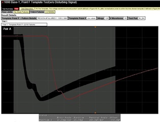
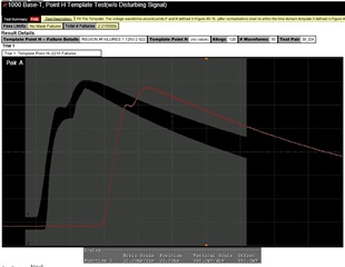
May we have advice for improving?
BR,
Kosaka
Hi Kosaka-San,
Thank you for sharing the waveforms. Can you please the waveforms in Testmode but without using the compliance software?
It will be easier to understand raw waveforms. The oscilloscope adds a filter to the waveforms.
Can you please measure the peak voltages of points A,B,C,D?
--
Regards,
Gokul.
Hi Gukul-san
Yes. it is only set the "TEST MODE" that is a Configuration Register 1 (CFG1), Address 0x0009. Not using other program.
Mesure with automaticaly with Agilent ociloscope.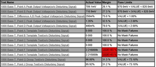
BR,
Kosaka
Hi Kosaka-san,
While measuring the envelopes of points F and H, the compliance software applies a filter on the waveform (this filter is specified by IEEE).
Can you please share the direct waveforms from the oscilloscope without using compliance software?
Here is the procedure
These unfiltered waveforms help us analyzing the issue better and to check if we can change settings to make the mask pass.
Here is the reference to points A,B,C,D, F,H
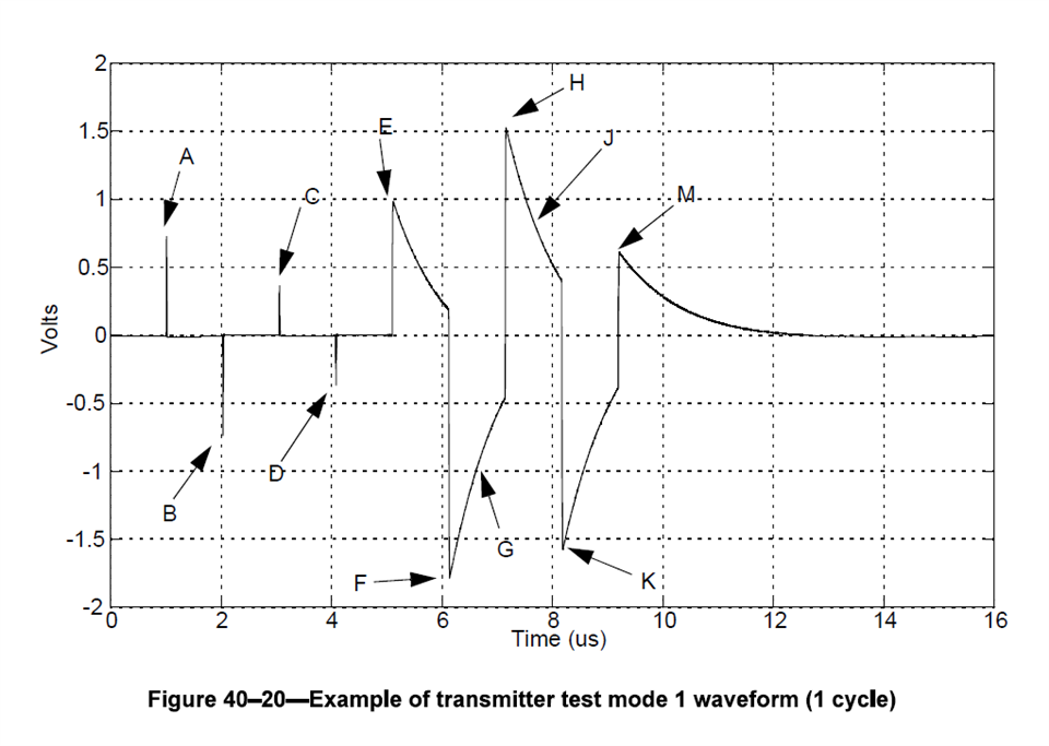
Please let me know if you need more details.
--
Regards,
Gokul.
Hi Gokul-san
We measured new board It become worse.
And this signal image is diffrent with example.
Could TI help us for truning?
whole signal image is below.
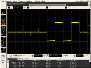
A
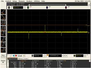
B
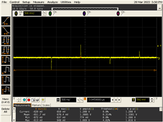
C
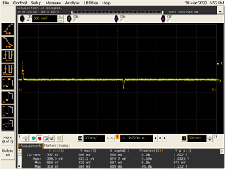
D
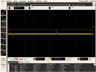
E
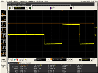
F
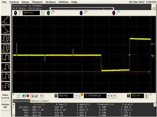
H
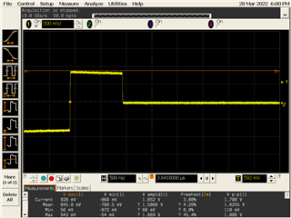
K
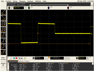
Hi Kosaka-san,
I'm interested to see the rise and fall behavior of these waveforms. The waveforms in the above images don't have a good resolution and we can't get the behavior of the rise and fall.
For this, can you please set your scale of x-axis to 16ns and recapture the waveforms?
--
Regards,
Gokul.
Hi Kosaka-san,
Thank you for sharing the waveforms. These waveforms give us the exact details about what rise or fall is causing the template fail.
Usually, the templates should pass with the default settings and the failure can be attributed to MDI side connections and layout.
I'm planning to do the following for the debug.
Please share your thoughts.
Can you please share the board schematic for review?
--
Regards,
Gokul.
Hi Gokul-san
Yes. We can share it.
Could we provide it with private transfer?
BR,
Kosaka
Hi Kosaka-san,
Thank you for sharing the schematic. We can take the debug offline.
--
Regards,
Gokul.