This thread has been locked.

If you have a related question, please click the "Ask a related question" button in the top right corner. The newly created question will be automatically linked to this question.

TPS65988DKEVM: PP3 power source in 988DK EVM

Part Number: TPS65988DKEVM
Other Parts Discussed in Thread: TPS65988DK

Hi team,

When I set PP3 as a power source on 988DKEVM, the system couldn't work.

When I set PP1 as a power source on 988DKEVM, the system could work.

The reason is PP3 and PP4 only could be power sink in 988DKEVM?
Jason

  • can you send your project file to review.  You should be able to setup the 988 to be source on the external power paths (PP3 and PP4).

  • Hi Alan,

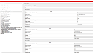
    I try to set up as external power path, but it can't work.

    If you open the the PP3 switch as output and change PP1 source to PP3, the circuit couldn't work.

    Could you please double check this, thanks.

    TPS65988DKEVM_U4924.pjt

    Jason

  • Can you send the project file for the configuration that does not work?  from what you are saying, you want PP 3 to be Source only, and then set one of your Source PDOs to use PP3.

  • Hi Alan,

    Update the FW.

    Please see attached file, thanks.

    Can't work verstion.pjt

    Jason

  • Hi Jason,

    Are you brining 20V into the barrel jack?  from what I can see, you are looking to have the following supported:

    5V, 3A

    9V, 3A

    15V, 3A,

    20V, 5A

    Since the EVM only support up to 3A using the internal power path, you are looking to use the external power path.  

    If I am correct with the above, I would setup PP1 Switch Config to Source Only, then also setup the PDO 1,2,and 3 (5V, 9V, and 15V) to use PP1 (since they only need up to 3A, and use PP3 for PDO 4 (20V,5A).  The issue with the way you have it is that if you try to put 20V on the barrel jack and set all PDOs to use the external power path, there will always be 20V on the Vbus, which will not work.  This is because you will be disabling the variable regulator that is set up to work with the internal power paths.

    Also, I see that you have Bank 1 set up.  not sure what this is for and does not look like it is needed.

    Regards,

    Alan

  • Hi Alan,

    I don't understand, according to datasheet TPS65988DK internal path can support up to 5A. why you said only 3A?

    I don't know why I need to use internal path for PDO1~3, and external PDO path for PDO4. if I only tune the PDO 4 to 20V/3A, it doesn't work too.

    Do you try the FW you provide to me on EVM board and it can work? 

    for my customer application, they only need to use external path, they don't want to use internal.

    Jason

  • Hi Jason,

    yes, the datasheet for the TPS65988DK sows the internal power path is 5A.  The EVM has a limit of 3A.  that is why I was suggesting using the internal up to 3A, then for 20V, 5A, setup the external.  anyway, as you want your 4 PDOs set up for the external power path, and you indicated you want to use the variable output regulator that is on the  EVM, this is what I suggest you do:

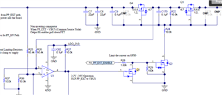
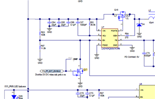
    1.  when you set up the external power path, the PA_PP_EXT_Enable trace enables the external power path, but it also disables the variable output regulators.  You will need to keep this from happening.  For PA_PP_EXT (PP3) you will need to remove Q17.  This will keep the regulator on.

    2.  The external power path, by default, is set up to be sink only.  You will need to remove Q3, which will eliminate the reverse current protection circuit, but still allow the external power path to be enabled.

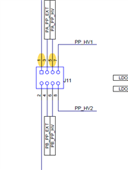
    3.  Jumper J11 pin 1 to pin 5 to allow the output of the variable regulator to go to the external power path.

    4.  if you need PB_PP_EXT (PP4) you will need to remove the appropriate parts for that path.

  • Hi Alan,

    Thanks for your information.

    For 1, can I jump the wire from R92 to GND. I think it will not disable the DCDC function.

    For 2, if I only use one port. it is ok I don't need tp remove the Q3 right?

    For 3. thanks.

    For 4, Got it.

    Jason

  • Hi Jason,

    1.  I would not jumper R92 to ground.  If you ground the side connected to PA_PP_EXT_ENABLE, you would be shorting that signal to ground.  You need that signal to enable the external power path in other circuits.  If you ground the other side (connected to Q17), you will be turning OFF the adjustable regulator... this is the opposite of what you want.  By removing Q17, you will allow the adjustable regulator to be always enabled.

    2.  By removing Q3, you will be disabling the reverse current protection circuit from shutting off the external power path (PP3) when you source current.  The board is set up to be sink only and this circuit shuts down the path if you have a reverse flow (Source).

    Regards,

    Alan

  • Hi Alan,

    1. May I know why only RCP circuit work when PP3 is sink. If PP3 is source the RCP circuit couldn't work?

    2.U3 is a comparator, I don't understand why the V+, V- both are connect to Vbus. how does this RCP work. Could you please explain this function to me, I am confused about that.

    Jason

  • Hi Jason,

    I just verified on my board (used a 65988DH EVM) that the removal of Q3, Q17, and setting the jumper as indicated above work.  I verified that I can source the appropriate voltage through the external power path.  I used a Power Duo board as SINK and cycled through the different voltages and verified VBUS with a meter.

    regards,

    Alan

  • Hi Alan,

    Many thanks.

    I know how to modify my board to become the source.

    Jason