This thread has been locked.
If you have a related question, please click the "Ask a related question" button in the top right corner. The newly created question will be automatically linked to this question.
Hello Guys,
I had posted article about my current project. But there was no active comment..
So I posted it again.
I assembled this pcb, and get nothing worked..
I've plugged in J1 which is upstream port for this hub, and there was no output on U6's LDO output
As I Know TIDA-01243 export power with only upstream input. but mine does not.
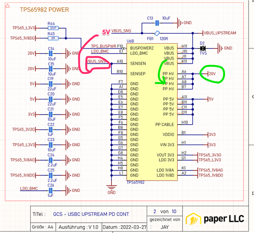
pls check my schematic, and tell me if there is something wrong.
Thank you,
Regard Bongjin,
Hi Bongjin,
Your schematic looks in order.
It looks like you have the dead battery RPD_G1/2 pins connected correctly so you should be able to receive 5V on VBUS even if the FW is not loaded.
Check the documents below for additional guidance:
I strongly suggest looking at the TPS65987D, since PD2.0 designs cannot go through certification anymore.
https://www.ti.com/product/TPS65987D
Jacob
Hello Jacob,
Thanks for your comment
When I plug USB-C PD( 90W) to J1, U6's H1 & B1 pin export 3V3
also VBUS_UPSTREAM measured by 5V but, PP_HV only out 2.16V
i have no idea why PP_HV out's 2.16V
As I expect, there must be 5V...
Do you Have any idea for that ?
I'm Planning to use TPS65988 since, I need one port for multi role, and another one will be PD in only..
Will it be correct?
Thank you,
Regard Bongjin
Hi Bongjin,
J2 is intended to be your input power to the dock, J1 would be 5V in only for bus powered operation.
Can you make sure that your component are placed correctly for the BUSPOWERZ pins to set which power path will close? Check the table above.
Yes the TPS65988 would be able to do this.
Jacob
Hello Jacob
Thanks, I did check the VBUSPOWERZ pin voltage, It was 1.8V
then my mode is VBPZ_HV right? and I plugged 5V USB-A to USB-C.
But my PP_HV pin export only 2.19V
Do i have to change my mode?
Thank you
Regard Bongjin,
That should work. Can you probe the CLK line going to the flash to make sure that the PD controller is attempting to read the flash? Lets make sure that the PD controller is powering up successfully.
Hello,
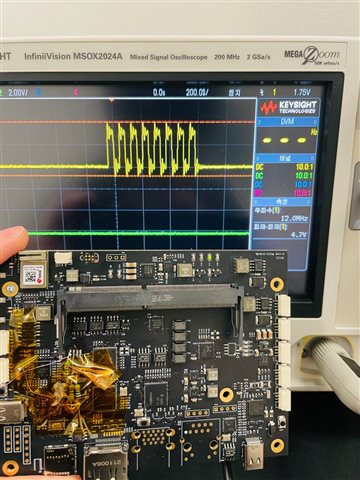
I probe the line, but SPI_CLK works properly !
and also uart to slave TPS65982 works well
Yes the SPI_CLK runs on 12MHz. Do you have the pjt file and the fw you loaded?
hello Jacob
I uploaded ti mini dock reference pjt, I uploaded with SPI eeprom uploader with binary output
Hi Bongjin,
I recommend looking at the parts around the PD controller to make sure nothing externally is causing issues. Check on all the power supplies.
From the schematic and using the minidock project the issue might be in layout or an external device.
Jacob
Hello Jacob,
You mean that my schematic has no problem, but possible problem must be outside of other power rail ?
I'll check 5V rail..
Thank you,
Hello Jacob
I plug USB-C to input connector, and check 5v out from VBUS_SNS
and i expect input from vbus goes to PP_HV pin right?
and also PP_5V out only 0V is it right ?
I've checked the connection and there was nothing strange...
Hi Bongjin,
PP5V would be 0V. PPHV should have 5V, could you confirm the the VBUS pins H11/J10/J11/K11 all have 5V also? You can probe on both sides of the FB1 to confirm.
Jacob
Hello Jacob
As you say, PP 5V -> 0V / PPHV -> 2.16V / FB1 and VBUS pin -> 5V
And i check the register with tool, but it says boot not ok.
is this can be the source of this problem ?
Hi Bongjin,
Can you read the Mode register also? I t looks like your SPI flash is not the board or maybe there is a pin out and placement issue.
Jacob
Hi Jacob,
I think something is wrong.. My tool keep tell me this value
I can check whole register, which register do you want to check ?
Hi Bongjin,
I am a bit tied up for the rest of the week. I will try to give you an answer tomorrow at the earliest.
Jacob
Hi Bongjin,
I checked the offsets and everything seems to be okay. Just to confirm did you create it with the Minidock project?
Jacob