This thread has been locked.

If you have a related question, please click the "Ask a related question" button in the top right corner. The newly created question will be automatically linked to this question.

DP83822IF: Can not test MII loopback mode between Xilinx Zynq Ethernet Controller and TI PHY DP83822 successfully

Part Number: DP83822IF

Hi everyone,

I have a customzied Xilinx Zynq-7000 board with TI DP83822IFR PHY chip. We are using PS7 GEM on Zynq as ethernet controller and operates in rgmii mode, 100Mbps.
I am testing MII Loopback mode of TI PHY chip. I configured DP83822 as following:

- Write 0x4000 into the PHYRCR register(0x001F): active software reset.
- Write 0x8000 into the BMCR register (0x0000): initiate PHY reset
- Write 0x6100 into the BMCR register (0x0000):enable MII Loopback mode and set the speed: 100 Mbps - full duplex
- Transmit packets from MAC to DP83822 PHY.
- Wait for Rx indication in MAC.

But I cannot receive any packet in MAC.

Does anyone know what I missed or I need to do to test MII Loopback between Xilinx Zynq and TI DP83822 successfully ?
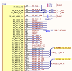
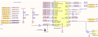
I also attach my schematic. I am wondering whether my hardware design has any problems ??

By the way, I am confusing about Phy Address value. Because RX_D[3:0] pins of TI PHY is not connect to any pull-up/pull-down resistor as attached schematic, PHY_AD[4:1] should be 3'b000, and Phy Address should be 1.
But I detected Phy Address is 31 (PHY_AD[4:1] = 3'b111).

Could anyone explain about it for me, please ?

Thanks in advance !!

Best Regards,

Dat Phung

  • Hi Dat Phung,

    Can you please provide the read out values of registers 0x0001, 0x0017, 0x0467, 0x0468? These register values can be polled before starting the MII loopback?

    To check the problem with PHY ADDR, can you please measure the pin voltages of RX_D[3:0] during the power-up? It is better to have waveforms of the supplies, RESET_N and the RX_D[3:0] pins overlapping on each.

    --
    Regards,
    Gokul.

  • Hi Gokul,

    Thank you very much for your reply !

    The value of registers as following:

    BMSR register: 0x7849

    SOR1 register: 0x0000

    SOR2 register: 0x0000

    RCSR register: 0x0241. I cleared "RMII Clock Select" bit (bit 7) before testing MII Loopback because we are using 25-MHz clock from crystal oscillator.

    PHYSTS register: 0x000C

    Is anything unreasonable in the above values ? 

    Thank you again !!  

    Best Regards,

    Dat Phung

  • Hi Dat Phung,

    The readings of SOR1 is inconsistent. This probably has to do with a problem accessing the indirect addresses. Can you please check the register reads? You can probably check if you see any non-zero reads of any register with address greater than 0x1F.

    Apart from this, I see that the PHY is in RGMII align mode on both RX and TX lines. Can you please check if the MAC is in shift mode (or internal delay mode) on both TX and RX side?
    It is easy to measure if the MAC is in shift mode on RX lines. You can probe the RXCLK and Data signals and measure the skew between them. The skew should be typically 2ns.

    --
    Regards,
    Gokul.

  • Dear Gokul,

    Thank you for your suggestion !

    I missed that SOR1 and SOR2 registers are extended registers. I'm really sorry about that. I have just accessed it by using REGCR and ADDAR registers, and obtained the values:

    SOR1: 0xFEBF

    SOR2: 0x000F

    I tried enabling RX internal clock shift and/or TX internal clock shift inside PHY DP83822 by writing  the combination of bits 12 and 11 (2'b10, 2'b11, 2'b01) in RCSR register , but testing is still unsuccessful.

    Best Regards,

    Dat Phung

  • Hi Dat Phung,

    There is something wrong with the strapping. All the straps except the one you have really strapped are reading mode 4 (1,1). The PHY address is also reading 11111. This means that during the power-up, all the pins are at a high voltage.

    Can you please measure the RX_D pins and if possible other strap pins during the power-up? It is better to have waveforms of the supplies, RESET_N and the RX_D[3:0] pins overlapping on each.

    --
    Regards,
    Gokul

  • Dear Gokul,

    I am going to check the waveform of strap pins, and share it for you later.

    But  I am confusing about the result of testing MII Loopback. I think MAC should receive loopback packet after I have setup Speed, duplex, enaled "MII Loopback" bit in BMCR register and reconfigured "RMII Clock Select"  bit in RCSR register to '0' (because  RX_DV strap pin has set XI_50 = 1). And  MII Loopback testing should be successful regardless of Phy Address.

    Could you please explain about it ? Thank you very much for your support !

    Best Regards,

    Dat Phung

  • Hi Dat Phung,

    The straps reads indicate that the pin voltages are high during power-up. We might have to check if the pins are always stuck to high voltage or it happens only during power-up. Incase, the pins are always stuck, then MII loopback fails.

    During the loopback testing, please check whether TX_* pins are toggling indicating data transmission from MAC.

    After all these checks, can you please follow the sequence below and let me know if this works?

    1. reg<0x001F> = 0x8000
    2. reg<0x0001> = 0x2100
    3. reg<0x0017> = 0x0241 (please choose bits 12,11 based on MAC shift/align mode)
    4. reg<0x0019> = 0x0000
    5. reg<0x0001> = 0x6100

    --
    Regards,
    Gokul.

  • Hi Dat Phung,

    Can you please let me know if you could resolve the issue?

    --
    Regards,
    Gokul.

  • Dear Gokul,

    I am so sorry about replying too late. I had some problems with my equipments. And I have just borrowed an oscilloscope.

    The following picture shows the waveform of measurements, with: Green : RX_D3 pin ; Yellow: Reset pin.

    During power-on process, Reset pin: 0.3 V ; RX_D3: 0.6V

    After finishing power-on: Reset pin: 1.8 V; RX_D3: 1.8 V within 50 ms, then remaining at 0V level.

    RXD[2:0] and RX_DV pins are same as RX_D3.

    Could you please let me know some advices about the above voltage results ??

    Best Regards,

    Dat Phung

  • Hi Dat Phung,

    Any reason why RX_D3 is high even when there is no pull-up resistance on the pin? Can you please check whether the MAC is driving this pin during power-up?

    Can you please capture the power supplies too during the same time?

    --
    Regards,
    Gokul.