Other Parts Discussed in Thread: TMS320F280025C, TCAN1145-Q1, USB2ANY
We are using TCAN1145-Q1 along with TI DSP TMS320F280025C. We want the sample code for the same. From where can we get sample code to configure TCAN IC using SPI?
This thread has been locked.
If you have a related question, please click the "Ask a related question" button in the top right corner. The newly created question will be automatically linked to this question.
We are using TCAN1145-Q1 along with TI DSP TMS320F280025C. We want the sample code for the same. From where can we get sample code to configure TCAN IC using SPI?
Also, one more question in addition to this , what is the default mode of TCAN IC. can we directly use it for CAN communication without programming it using SPI, if default mode is normal mode?
Hi Yogini,
Please send me an email to request the sample c drivers for TCAN1145. You can find my address in my E2E profile by clicking on my name.
The default state of this device is Standby mode where the CAN transceiver is not active. To evaluate the CAN transceiver, the device will need to be moved into Normal mode using SPI.
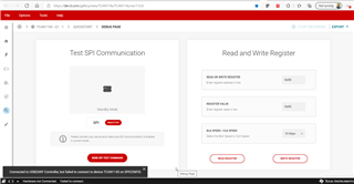
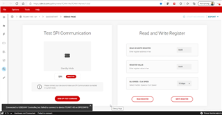
The EVM also has an MCU built in that facilitates simple configurations such as this. You can use the standard USB2ANY interface to send direct SPI messages, or use the dedicated TCAN114x GUI available online at the link below to quickly configure the IC using a USB connection from a PC.
https://dev.ti.com/gallery/view/TCAN114x/TCAN114x/ver/1.0.0/
Let me know if you have questions on the code or the GUI.
Regards,
Eric Schott
thanks Eric . I emailed you from my mail id for C drivers. Meanwhile , I am also checking GUI only to evaluate modes. But I am getting below error when I connect EVM board with Mini USB. Whatlese I am missing here.
Hi Yogini,
Thanks for sending that over. I have responded to your email with the demo drivers. Let me know if you have any issue opening the attachment.
It appears that the MCU on the EVM is not getting a response from the transceiver. Is the TCAN1145 properly powered? Vsup and Vio will need to be present for SPI to be active. Also make sure that the switches on the back of the EVM (S7) are switched on to enable the connection of the MCU and transceiver.
Regards,
Eric Schott
Thanks Eric. I am able to connect to GUI now. I tried changing modes and modified registers as well. Now, I am testing CAN communication. I have just written the CAN data registers and DLC. I want to observe CANH and CANL signals. But how do I establish CAN communication between vector device and on board processor through TCAN?
When directly tap the CANh and CANl lines on scope, I do not see any signals there.
Hi Yogini,
I'm glad to hear the GUI is working well!
The MCU on the TCAN1145 EVM does not have a CAN controller built in. It is only used for configuring the device through SPI. A separate device will need to be used to generate and receive CAN communications on the TXD and RXD lines.
Regards,
Eric Schott
Hello Eric,
Now I tried connecting TCAN to my controller, TMS320F280025c. I connected 4 spi connections and CAN Tx Rx pins.
For powering the TCAN, I used USB only, same as previous connections. But with these connections,I am not able to connect to tcan using GUI.
Do I need to provide external power to TCAN rather than powering it using USB? (while using external controller?)
Also, from where I can set the SPI data rate of TCAN? I am not able to get the register for it in datasheet.
In tcan init, I am just puting tcan IC into normal mode. whatelse I should do to initialize tcan , only to communication over SPI , and CAN (500K baud rate)?
Hi Yogini,
The SPI interface for TCAN1145 is used for configuration and mode control. This can be done either through the GUI for quick evaluation or through an MCU's SPI port to closer emulate an application or to test code. The TXD and RXD pins are used for CAN data that interface directly with the CAN bus (CANH/CANL). Because the GUI only has access to the SPI pins, CAN data needs to be sourced from another device (MCU or signal generator). I do not recommend attempting to control SPI from both the GUI and an external MCU. Only one or the other should be used for SPI.
The TCAN1145 needs to have Vsup supplied in order to function in any mode. In active modes (Normal and Listen), Vcc and Vio are also required. The USB on the EVM can only provide 3.3V to Vio via the J2 configuration. It is recommended that Vsup and Vcc are supplied to the EVM using an off-board supply. If the transceiver is connected to an MCU, Vio should share the same voltage as the MCU's IO (this is why 3.3V is available from the USB, to share with the on-board MCU).
Because SPI is a synchronous data protocol, the SCLK signal provides the clock source for TCAN1145's SPI interface. These is no need to set the SPI rate of TCAN1145. The SPI data rate must simply be within the operational range of the transceiver (max 4MHz).
Regards,
Eric Schott
Hello Eric,
thanks for the detailed description. This is really helping me to progress.
Now, I have connected external power to TCAN EVM and SPI connections with TMS320F280025C.
I am only trying to read the mode of TCAN using SPI and also writing the mode if it is other than normal mode.
But something is missing. I am getting unexpected value. Below is my code. Let me know if anything is missing here.
For reading the mode:
uint16_t tData;
uint8_t intRegister = 0;
uint8_t *data;
uint8_t address = 0x10;
while(SPI_isBusy(SPIA_BASE));
SPI_readDataNonBlocking(SPIA_BASE);
SPI_writeDataBlockingNonFIFO(SPIA_BASE, (uint16_t)0x00);
SPI_writeDataBlockingNonFIFO(SPIA_BASE, (uint16_t)(address << 1)); // 0 for read((address << 1)|0x01)
SPI_writeDataBlockingNonFIFO(SPIA_BASE, (uint16_t)0x00); // Feed dummy zeros for read
SPI_writeDataBlockingNonFIFO(SPIA_BASE, (uint16_t)0x00);
while(SPI_isBusy(SPIA_BASE));
tData = SPI_readDataNonBlocking(SPIA_BASE); // Pull first byte
intRegister = (uint8_t)(tData & 0xFF);
tData = SPI_readDataNonBlocking(SPIA_BASE); // Pull first byte
*data = (uint8_t)(tData & 0xFF);
Hi Yogini,
I'm glad to hear things are progressing in the right direction
I'm not familiar with this SPI driver directly, but at a high level this looks correct. You are correctly shifting over the register byte and leaving a 0 in the least significant bit to indicate a read. The dummy zeros are good to create SCLK pulses for TCAN1145 to return the data in registers 0x10 and 0x11 (overrun bytes will extend into the next register). Without knowing the results of the data you pulled though, it's hard to comment if this looks successful or not.
A couple thing I will mention though:make sure you have configured the SPI to use the proper chip select and serial clock polarity.
TCAN1145 uses negative polarity for chip select (nCS) and will become active when nCS is pulled low. When nCS goes high again, this will indicate the end of the SPI transaction. nCS must go high between each SPI transaction (read or write), but can be kept low for extended read/write commands.
TCAN1145 uses the rising edge of SCLK to sample SPI data on SDI and changes SDO data on the falling edge of SCLK. Make sure the SPI controller is configured to use this same type of logic or you may get garbage data between devices.
Regards,
Eric Schott
below are the values I am getting, when I send only one 0x00 after writing an address;
also, if I try to burst read 3 bytes with below code, I am getting only 0x54 for every data value.
//multiple register read
while(SPI_isBusy(SPIA_BASE));
SPI_writeDataBlockingNonFIFO(SPIA_BASE, (uint16_t)(address << 1)); // 0 for read
while(SPI_isBusy(SPIA_BASE));
tData = SPI_readDataBlockingNonFIFO(SPIA_BASE); // Pull first byte
intRegister = (uint8_t)(tData & 0xFF);
uint8_t i = 0;
for (i=0; i < 3; i++)
{
SPI_writeDataBlockingNonFIFO(SPIA_BASE, 0x10); // Feed dummy zeros for read
while(SPI_isBusy(SPIA_BASE));
tData = SPI_readDataBlockingNonFIFO(SPIA_BASE); // Pull data byte
datab[i] = (uint8_t)(tData & 0xFF);
}
while(SPI_isBusy(SPIA_BASE));
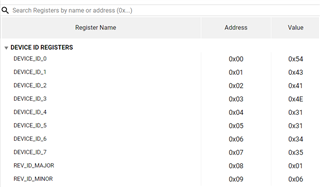
As per GUI, below are the expected values for registers;
I want to read the the register 0x10, whose value should be 0x01, or 0x04 or 0x07; in sleep or standby or normal mode. But I am only getting value = 0x54 , which is the value of register 0x00.
I don't know what am I missing in the code.
Hi Yogini,
I agree, it sounds like the transceiver is only seeing 0x00 as the address, and is therefore returning the DEVICE_ID value. Apologies, but I'm not familiar with the SPI driver so I don't think I'll be much help in debugging the code here apart from at a high level. My recommendation would be to connect an oscilloscope or logic analyser to the SCLK, SDO, and SDA lines and monitor the SPI frames. This will let you correlate which function calls correspond with what physical SPI actions. This would also help you check and see if the format of the frame is matching the requirements shown on the TCAN1145 datasheet.
Regards,
Eric Schott
Hello Eric,
Good news is I am able to establish the SPI communication now.
Now I will focus on CAN communication. As per my understanding , I don't have to do anything specially for TCAN rather than connecting TX RX from controller to TCAN controller. is it correct?
Hi Yogini,
Great to hear!
Correct. All CAN data is transmitted using only TXD and RXD. The transceiver will need to be configured to Normal mode via SPI in order to properly interface with the CAN bus.
Regards,
Eric Schott
Hello Eric,
I am able to set CAN communication in normal mode. Thanks for your help.
I have few doubts;
I have gone through the datasheet , but I am not able to find it.
After how much time the TCAN IC enters into standby mode from normal mode, when there is no CAN Bus activity?
I have read in data sheet that, tSILENCE is the timeout for it. and it ranges from 06 s to 1.2 s.
But what is the exact value? Is it configurable? if yes, then how?
Hi Yogini,
When there is no CAN activity for t > tSILENCE, the SWE timer starts. Once the SWE timer (~4 minutes) expires, then the transceiver will automatically switch to Sleep mode. By default (CANSLNT_SWE_DIS = 1), any CAN activity will clear the tSILENCE timer and reset the SWE timer. This means that there needs to be a full 4 minute gap in CAN traffic before the transceiver will automatically go to Sleep. The tSILENCE interrupt can also be cleared manually through SPI to prevent the transceiver from going to Sleep for another ~4 minutes.
The actual times of these timers, 0.6s - 1.2s, 3.75min - 5min, is not configurable. They are specified by the device and the ranges are given to cover the internal clock behavior across all operating conditions.
Regards,
Eric Schott