This thread has been locked.

If you have a related question, please click the "Ask a related question" button in the top right corner. The newly created question will be automatically linked to this question.

DP83867E: TI - DP83867 Bring up issues

Part Number: DP83867E

Hi Team,


Good evening,


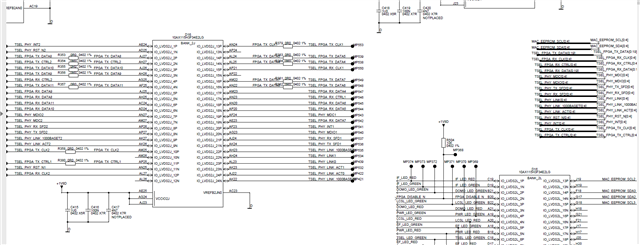
We need your support urgently on the TI - DP83867 Bring up issues. We are using the Arria10 Intel chipset FPGA to interface with TI PHY chip.

We have captured the signals during the bring up. Please go through the captures and suggest the debug instructions if we miss any (Captures shared with Shinu Mathew vmshinu@ti.com in mail)?


Also, we are unable to make MDIO register access. My Team said that NIOS software is used and they are not familiar with MDIO register access. It will be great if you have any inputs on how to access MDIO registers will be of great help.


Best Regards

Srikanth

  • Upon board bring up, we see 2.5MHz clock signals on RGMII RX_CLK signal. This proves that configuration is not 100%. The PHY must autonegotiate to 1000mbps, which must result 125MHz on RX_CLK from PHY chip to FPGA MAC. This is not achieved till now.

    Please hint or share any ideas to make this MDIO register read and write operation from FPGA to PHY chip. Currently we are unable to make that MDIO communication because of no one knows how to do that with NIOS.

  • Hi Srikanth,

    All SMI details are located on section 8.4.2 of datasheet. Please ensure that FPGA can follow requirements set in section. Another thing to make note of is which PHY address that DP83867E is set upon. This is set via strapping and trying to talk to the PHY with an incorrect address would cause non-responsiveness. 

    Switching to link issues, can you confirm that you are able to see CLKOUT pin and that power supplies are at desired voltages? What link partners have you connected PHY to? What cable is being used (length and type)?

    Would it be possible to attach schematic for review? In the meanwhile, I will contact FAE regarding scope captures.

    Another helpful reference to go over would be SNLA246.

    Sincerely,

    Gerome

  • Hi Gerome

    Please find my inline response.

    In our case MDC, MDIO is not seen on the traces after power up, i.e after PHY RESET deasserted. Is it mandatory to find the MDC, MDIO signaling after powerup?

    Our product is using NIOS software and Client supplied Ethernet IP. If at all any MDIO communication has to happen, it must be driven from Client Ethernet IP.  But unfortunately the FPGA team member not able to initiate this transaction to read any internal registers.

    PHY address is set to 0000. Please see the strap settings from schematic below

    Power supplies are perfect. Please see the values measured in below snapshot.

    CLOKOUT is not checked. We didn't assign any test point. No access to capture using probe. Please provide any idea to capture it if possible.

    Link partner from external board. FPGA chip on our board is Client (Slave) and FPGA chip on external Bridge board is Host. Cable used is Cat5e. I need to check the length of it. I will revert on this shortly.

    Schematic is attached for your reference.

    Since the link is not established , RGMII_RX_CLK shows 2.5MHz. we are unable to check any RGMII signals and their timing as those signals are not up and running. I am assuming it is due to the PHY chip is not 100% initialized.

  • Hello,

    Thank you for sharing your schematic. I will look to get feedback on this by EoD 3/25 at latest. Would it be possible to also share the full MDI subsection? I would like to see the magnetics configuration and where those signals end up.

    Sincerely,

    Gerome

  • FPGA side Media independent side connections

    Block level connection shown below from ETHERNET PHY CHIP TO RJ45

    RJ45 connections shown below. But we realized pin assignment mistake in RJ45. We made the external cable to fix that.

    we made cable connection swap to have the intended connection. But still PHY chip not configured perfectly.

    May I ask if you have received the PPT which I shared with FAE (shinu mathew) vmshinu@ti.com?  If not, please find the same in the PPT attached in this chat.ds

    SrikanthTI PHY-DP83867_chip Measurements.pptx

  • Sorry I missed adding Magnetics Schematic. Please find the same here.

  • Hi Srikanth,

    Thank you for the schematics. Looking forward to getting you feedback soon!

    Sincerely,

    Gerome

  • Hi Srikanth,

    The best way to probe clockout without test point would be with the pin directly.

    This would be the only way I see to connect it. As link and SMI seem to be the problem you are facing, I would like to go through the basic checks to ensure a functional PHY.

    - It appears the PHY's auto-negotiation feature is enabled. You can also probe the MDI pins while the cable is disconnected to see the presence of FLPs.

    You mentioned you are not seeing MDC and MDIO after reset deasserted. MDC is a signal supplied by the external controller, not the PHY, so you would need to check with that specific vendor that supplies the external controller. If external controller is sending the clk signal and MDIO signal to read, but PHY is not responding, then we can view more into PHY being uninitialized. However, if the line is high all the time, then I would suggest looking at the controller.

    - Please also ensure that MAC is not sending any packets during PHY powerup. This can interfere with strapping timing and PHY can miss-sample if the voltage on the node is not solely driven by the strap resistor network.

    Sincerely,

    Gerome

  • Hi Gerome,

    I could able to collect few measurements for Ethernet interface. Rbias voltage is fine. MDC clock is driven by controller with 4.8MHz. But MDIO is struck HIGH. No transactions seen on MDIO. Please refer below measurements and let me know if there is anything to suspect?

  • Hi Srikanth,

    MDIO is also driven by the external controller for the initial half of the communication. Only when it is reading does the PHY take control of the line.

    You would need to check the external controller as that will be driving the line. If MDIO is never toggling, that means the external controller isn't polling for the PHY. Please refer to Table 3, and figures 17 and 18 for timing diagram regarding MDIO and MDC.

    Could you also please confirm presence of CLKOUT signal?

    Sincerely,

    Gerome

  • Hi Gerome,

    Testing happening at remote location. I didn't receive the results as this test was kept on hold. I will confirm as soon as we resume testing next week.

  • Hello,

    Thank you for the update. I am looking forward to your results. As discussed before, please take a look at the external controller as it seems MDIO is not toggling and bring this up with the appropriate party.

    Sincerely,

    Gerome

  • Hi Gerome,

    I found some length mismatches in my board. Lenth matching is more than 20mils. I am using 5 Ethernet ports. The lengths are captured in the attached PPT. Can you please confirm if the existing routing length match deviation is ok for 1000mpbs? Could this be the reason for the Ethernet link is not coming up ?

    RGMII Design details.pptx

    Best Regards

    Srikanth

  • Hello,

    Thank you for your reply. Please see section 9.2.2.2.1 for MDI layout guidelines.

    Sincerely,

    Gerome