This thread has been locked.

If you have a related question, please click the "Ask a related question" button in the top right corner. The newly created question will be automatically linked to this question.

PCA9548A: Using multiple MUX on the same microprocessor SCL / SDA lines

Part Number: PCA9548A


 Keep in mind that I have not done any experimenting with these chips...only looking over the data-sheets. And, I am not experienced with !2T:

I have a single microprocessor to which I would like to attach more than eight I2T sensors.

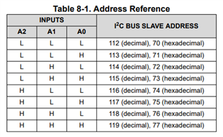
The data sheets everywhere show A0, A1, and A2 always connected to ground, giving A0=A1=A2= 0. But the description says that these pins can also be connected to Vcc, giving any pin so connected an address value = 1.

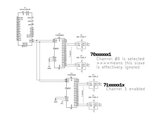
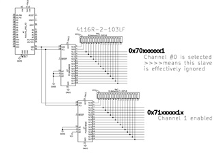
From this, it seems that I can connect multiples of these MUX '9548 to "fan out" to 8, 16, 24 (...etc) sensors which, individually, do not have unique addresses.

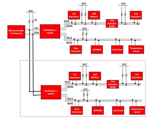
The diagram above is copied from the TI bulletin, Understanding the I2C Bus (https://www.ti.com/lit/pdf/SLVA704), which has been modified to show the fan-out to a 2nd MUX.

Am I on the correct track with this arrangement??

  • Hello,

    First you can use the 3 address pins to give you 8 different unique addresses for your MUX. The datasheet goes over all possible combinations with the address pins:

    So like you said you can add up to 8 muxes and control each one independently. Now in order to read each of your sensors, if they all have the same address this is exactly where the mux would come in handy. You would use the mux to decide which sensor to connect to the bus. Keep in mind if all the sensors have the same address they should not be connected to the bus at the same time. You could leave a bus open on each mux that is not connected to a device and when you want the mux to not connect to any device you would select that bus. This would give you 7 sensors per mux.

    This is what I suggest your I2C topology looks like. It will give you the ability to control everything through I2C writes.

    Now if you want to get 8 sensors per mux you can disable the device by disconnecting VCC from the device. This is the best way to disable the device. However, this will most likely require other components. You can also just hold the device in RESET by pulling the nRESET pin low. However, this is not recommended especially on our older devices that had stuck bus issue when reset was toggled.

    Let me know if you have any other questions.

    Best,

    Chris

  • Hello--thanks for the fast and helpful response. I just need to make sure I understand this explicitly. What I understand so far is:

    1. Yes, I can fan-out several PCA9548a slaves on a bus from the SCL/SDA of my microcontroller
    2. Each slave will have a hard-wire (GND or Vcc to A0, A1, A2) address
    3. If I desire to connect to a specific sensor via one slave, I need to essentially disconnect the inputs from all the other slaves by addressing Channel 0 on all of the other slaves before I read the data from my desired sensor
    4. If I leave the slave's Channel 0 disconnected, I don't have to do perform any resetting or disconnecting operations.

    Please see the attached drawing, and the questions, below

    Questions:

    The channel 0 null connection: Should this be tied to ground? Should I use a capacitor or a resistor in any connection to ground? Or is it safe to just let it "float" ?

  • Yes this is how I would do it your set up looks good. Just remember you are going to need pull up resistors on all your SCL/SDA lines to VCC. This includes your open bus SC0 and SD0. Just pull them up to VCC with a pull up resistor. You can use a weak on like 10K since this bus will not be communicating. You cannot connect this bus to gnd because that will hold your SCL rail and SDA rail at ground and you will not be able to communicate on the I2C bus. This is the same concept with leaving it floating. You do not want any noise to pull these pins low by accident since that can hurt your I2C communication.

    Best,

    Chris

  • OK, so here is what I have now, as per your recommendation:

    Regarding the Reset pin....should it be held HIGH by a pullup to Vcc, as well?

    This has resolved my issue, BUT, if anyone can help me with a lucid example of the Arduino IDE code that I would use to address an individual sensor, that would be great!

    Thanks!!!!!

  • Em,

    This looks good just make sure that your pull up resistors are valued correctly for your sensors. We have a great document on how to calculate pull up resistance

    The reset pin should have a pull up resistor to VCC. I'm not sure if you are designing a PCB but if you are I would reccomend using 0 ohm resistors as pull up/ pull down on your address pins so that you have the ability to change the address of the MUXes if you want to by simply populating a resistor or depopulating one. 

    Some things to keep in mind:

    • make sure that the sensor address won't conflict with your MUX address.
      • Just make sure they are not the same address.
    • When you are programming your Arduino make sure only one channel is enabled at a time.
    • Lastly make sure that the VOL of your Arduino is compatible with the VIL of your I2C sensor.
      • This is where you can change your pull up resistance to make it weaker so that your VOL is lower. I'm not too familiar with the Arduino devices but I would assume they don't have some static offset voltage . But just incase it does you want to make sure that it is compatible with your devices VIL.

    Also, this E2E website is here to provide help with TI products. We have an MSP430 forum that can help you with that device but we do not have a forum for Arduino devices. If you want generic help on what data to send on the I2C bus we can help with that.

    Best,

    Chris