This thread has been locked.

If you have a related question, please click the "Ask a related question" button in the top right corner. The newly created question will be automatically linked to this question.

THVD1512: termination resistor RT

Part Number: THVD1512

Hello,

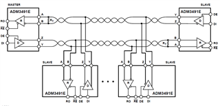
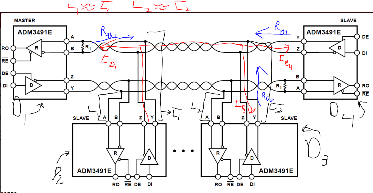
The customer is looking at page 18 of the THVD1512 data sheet, Figure 23. Typical RS-485 Network With Full-Duplex Transceivers.

The master is connected to two slaves.
One of the slaves has a termination resistor RT connected, but the other slave has no termination resistor RT.

Is termination unnecessary?

Best regards,
DDdoor

  • Termination resistors must be (only) at the two ends of the bus.

    (If you removed the transceiver at the right, you would still need the resistors there.)

  • Hi DDdoor,

    Clemens is correct.

    For RS-485 systems there are 2 termination resistors suggested (typically 120 Ohms as the termination resistors in parallel equals to 60 Ohms). If there are more than two transceivers on the line only the transceivers on each end of the transmission line are terminated. 

    If you have any other questions please let me know!

    Best,

    Parker Dodson

  • Hello Clemens,

    Hello Parker,

    Thanks for your reply.

    You mentioned that only both ends are placed, but what is the definition of "both ends"?
    Are they the two points with the longest distance?
    Or can any two points be used?
    Also, what are the issues when multiple terminating resistors RTs are connected?

    Best regards,
    DDdoor

  • The end literally is the end of the cable. It is the point where current cannot flow any further.

    Additional resistors do not terminate anything, and would just increase the load, i.e., they would reduce the noise margin or even make communication impossible.

  • Hi DDdoor,

    It is the physical ends of the cable  where signal can not longer travel as Clemens mentioned. 

    Adding more terminating resistors is will increase the loading on the bus. RS-485 transceivers are rated to drive a 54 Ohm Load with a voltage of 1.5V. Adding more than 2 120 Ohm terminating resistances will increase the load (for example if there are 3 120 Ohm terminating resistors the driver will see 40 Ohms which requires a stronger drive than RS-485 is spec'd too. The more resistors the worse this gets. So this is not recommended to do and only the 2 terminating resistors are recommended. 

    If you have any other questions please let me know!

    Best,

    Parker Dodson

  • Hello,

    Attached is an example of ADM3491E configuration.
    In this example, there is no RT inserted on the transmit side.
    Is it possible to have this configuration with TI's THVD1512 as well?


    Best regards,
    DDdoor

  • Electrically, the THVD1512 and the ADM3491E (and all other transceivers) behave the same.

    A termination resistor is not needed at a device that is a transmitter. However, if one of the slaves at the bottom is transmitting, then the two transceivers at the top are not transmitting, and you will get reflections at their unterminated Y/Z outputs. That example configuration would be correct only if the two slaves at the bottom never transmit anything.

  • Hi DDoor,

    Clemens is correct by saying the devices are electrically similar. This configuration is possible but it does come with risks.

    In an ideal situation RT = Z0 of the transmission line so that reflections = 0 since the reflection coefficient = (ZL-Z0)/(ZL+Z0). However due to tolerance of the passives and cable characteristic impedance there will be some reflection. Since the RX is not terminated it will reflect any incoming reflection back onto the line without much, if any,  attenuation. This typically isn't enough interference to cause major issues as this reflection will decay pretty quickly, but it could degrade the max distance of the device.

    With respect to the two bottom devices in the diagram - if they ever transmit their will be a lot of reflections - as Clemens mentioned as the bottom two devices send the signal to the entire line (essentially both ends of the cable are seen as the "load" - the other bottom device can be ignored - this is explained a little lower in the post) and since one side is unterminated there will be a large risk of data integrity issues due to the reflections from the unterminated side.

    See below for a diagram showing reflection pathways:

    L1 = L1_bar ; L2=L2_bar. These are the stub lengths of the two bottom devices. If L < (tr/10 * v * c) - where tr is the rise/fall time of the transceiver, v is the signal velocity of the transmission line as a fraction of c, and c is the speed of light - then these devices can be ignored as reflection sources - however if that isn't true they can't.

    In the above figure D2 is transmitting; I_D1 is the incident signal into D1, I_D4 is the incident signal into D4, and I_D3 is the incident signal into D3. R_D1, R_D4, and R_D3 are the resulting reflections from each of those signals.

    If the length condition is met for both L1/L1_bar and L2/L2_bar we can assume R_D3 ~ 0. Since D1 is terminated R_D1 ~ 0. However, since D4 is unterminated R_D4 ~ -1 * I_D4 which can cause integrity issues.

    If the length condition is not met there could be even more reflections possible.

    So in conclusion in this setup only D1 and D4 can transmit without many issues as long as L1/L1_bar/L2/L2_bar < (tr/10)*v*c; there will be some reflection but it shouldn't cause problems until you are near maxing out the distance of the transceiver. However D2 and D3 will not be able to transmit cleanly due to the lack of termination of D4; if the length condition is not met there could be even more reflections.

    To avoid the above complications terminate both ends of the cable and keep stub length of the bottom devices (in this case D2/D3) less than 1/10th of the fastest signal transition on the bus.

    Please let me know if you have any other questions.

    Best,

    Parker Dodson


  • Hello,

    Thanks for explaining in detail.

    Do you have any documents you would recommend for a customer to use in designing a circuit for the THVD1512?

    Best regards,
    DDdoor

  • Hi DDoor,

    Please see the RS-485 Design guide here: https://www.ti.com/lit/an/slla272d/slla272d.pdf?ts=1648672970949.This document should go over most of the basics of RS-485 design (I added some information on stub lengths as a few slides below as well). Section 12.1 on page 8 of this document links to multiple other documents to delve into the nuance of each topic - they aren't necessarily needed as the design guide should cover most of it - but it could be a source of more information as well. 

    I don't have an app note for the following information, but I do have a few slides, shown below, that also go over how to connect multiple devices:

    This is for the device that are unterminated (the traceivers not on either end of the cable)

    Here is the equation on stub length that I shared earlier - with some common max distance on a few of our parts:

    Best,

    Parker Dodson