Part Number: SN65MLVD200A
Hello forum,
I have a question to the device “SN65MLVD200A”.
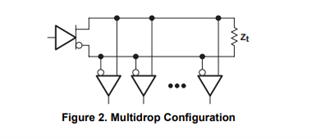
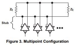
I found a document “Multipoint-Low Voltage Differential Signaling (M-LVDS) Evaluation Module” somewhere on the TI website. Sorry, I can’t find the current link anymore, but it is from April 2004 and does have the name “SLLU039B”. I have a question to the Figure 2-3 on page 2-4.
I’m planning to develop some test hardware and I want to use a SN65MLVD200A device per hardware. I want to explain it in an example.
Hardware 1 is a leader board and can send additionally commands to three follower hardware’s via a separate bus (Not via M-LVDS). The separate bus can be used to switch the necessary 100 Ohm resistors to the different follower devices. The leader board does have the 100 Ohm resistor directly connected to his two Differential I/O pins A and B.
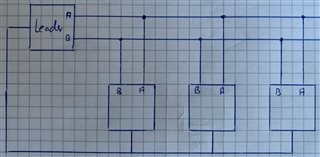
My question is, can all Differential I/O pins (A and B) from the SN65MLVD200A follower devices be connected together to a M-LVDS bus? And when the leader board wants to talk to on of the three follower boards only the addressed board switches his 100 Ohm resistors to the M-LVDS bus?
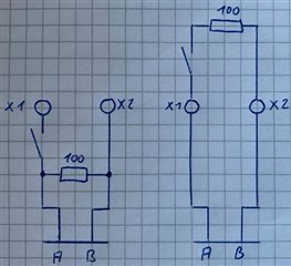
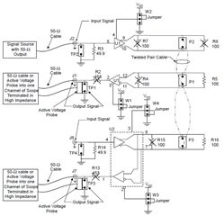
On the picture above two different connections are shown. The connectors X1/X2 should explain the connections to the M-LVDS bus.
On the left side the resistor is between the connectors X1 and X2 and the pins A/B.
On the right side the pins A/B are connected permanently to the M-LVDS bus and only the resistor can be switched to X1 and X2.
My first thought was that it is electrically nearly the same but in my first picture (from the TI document) the connectors P1/P2/P3 are also between the pins A/B and the resistor.
At first, I thought it didn't matter, but unfortunately, I found out that it didn't. I did first tests with two SN65MLVD200A devices where I soldered the two 100 Ohm resistors directly to the pins A/B. I noticed that this did not work very well for me. I wasn't satisfied until I moved the resistors farther away from the A/B pins. That is the reason why I think the right side from the last picture is the better idea. Although it's almost the same electrically, it's a bigger difference for the development of the test hardware.
The intention of this forum post is that someone can confirm me that the resistors need to be further away from the pins.
Then, of course, the question arises as to how far away these resistors have to be or whether there is a recommended circuit for the 100 Ohm resistors.
I would be very happy about an answer. Thank you and best regards.