Part Number: AM26LV32
Hi Team,
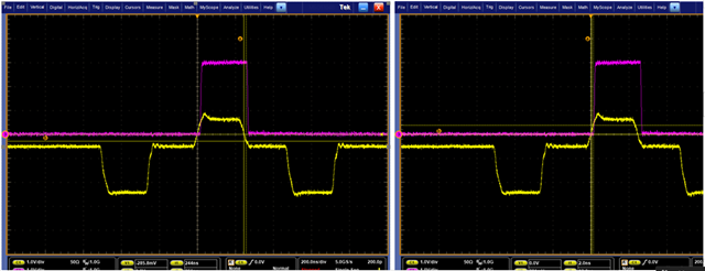
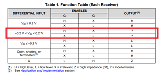
For the below red frame logical output part, customer is consulting whether the logical output state will follow previous state here? Or just no-sure that? Thanks.
Best,
Stanley
Part Number: AM26LV32
Hi Team,
For the below red frame logical output part, customer is consulting whether the logical output state will follow previous state here? Or just no-sure that? Thanks.
Best,
Stanley