This thread has been locked.

If you have a related question, please click the "Ask a related question" button in the top right corner. The newly created question will be automatically linked to this question.

SN65MLVD207: Bidirected signal with one wire

Part Number: SN65MLVD207

Hello,

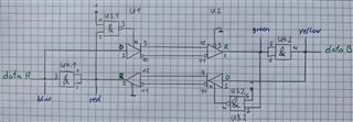
I have a question. I’m planning to transmit a bidirectional signal via two SN65MLVD207D devices.

It is based on a bidirectional signal that has so far been transmitted via a single wire. There is currently no way to detect if the signal is going to the one or to the other way. This means that there is no way to control both pins DE or /RE pins on the respective chip.

Is there may be an idea how a circuit can look like to make it possible to transmit such a signal with this chip? The signal voltage does have 3.3V

Best regards,

Marcel

  • Hi Marcel,

    Can you give me a better idea of your system architecture? Do you have control of the source? There is no general purpose circuit that can make this process autonomous using only this device but I can try to come up with some ideas based on your system.  

  • This is not possible with the SN65MLVD207 or any other LVDS transceiver. You have to use a singe open-drain signal (like I²C) or a differential signal with dominant and recessive states (like CAN). See here for a list of 3.3 V CAN transceivers.

  • Hi Marcel,

    Any additional support needed here?

  • Hello ,

    I have an idea in my mind. But I want first try it directly with the SN65MLVD207D chip. But I have a problem here in Germany to get those devices. I've ordered from two major electrical companies (RS and Mouser), but both can't seem to deliver. I've been waiting almost two weeks. I'll report as soon as I've been able to try out my idea. Then I come back if I have further questions if that is OK.

    Best regards,

    Marcel

  • Hi Marcel,

    Understood, you may also consider contacting your TI sale rep or order from ti.com directly.

  • Hello, sorry for that delay. It tooks a looooong time to get my preferred devices. I had to wait two further weeks.

    I had an idea in my mind, and I think it works as I expected. My idea is to transfer a Microcontroller SWD signal via LVDS. The problem is that the DIO signal is a bidirectional signal.

    After some little tries, I came up with this idea:

    U3.x is used to ensure that no echo came up via the “D” signal when something will be received from the “R” line.

    U4.x serves as a diode so that signals can only be transmitted in one direction.

    My experimental setup looks like this:

    First, I applied a low-frequency signal from about 15 Hz. I connected this low frequency to the two different inputs “data_A” and “data_B”. In the following pictures it is visible that it seems to work.

    Data_A signal:

    Data_B signal:

    So, I did my tests and connected on “data_A” the SWD -DIO signal from a programming interface and on the other connection “data_B” a controller board.

    I have the possibility to change the SWD interface speed. When I set the signal to 2000kHz it was possible for me to download a file into the controller. With 4000kHz I get communication errors.

    My question to TI is now if this is more a kind of random result or could this be a stable state?

    Did TI have experience with such circuits?

    I did the experience that it is with such signals always difficult to use a primitive board that I used. Of course, I would develop a circuit board, but I would be interested in the opinion of TI experts again.

    Is it possible for someone from TI to tell me if this is a good idea and give me a hint if I'm on the right track here?

    I currently do not have enough experience with such LVDS chips. But I'm quite willing to learn it. Slight smile

    Best regards.

  • Hi,

    I do not see any logical issues with your design since you are disabling the driver when data is received. At lower frequencies this seems reasonable. at high frequencies I would be concerned with the switching speed of the and gates you are using to disable the LVDS drivers.  As you pointed out moving to 4000kHz signal yielded communication errors. This was caused by signal degradation of the single ended wires and bread boards used on the LVDS side. the single ended singles SNR look reasonable but this may not be the case for differential signals.

    You may find the below document useful in familiarizing your self with LVDS: 

    https://www.ti.com/lit/snla187 

  • Hello Malik,

    thank you very much for your reply. That sounds good for me.

    Thank you also for the link. I will have soon a look to it. Perfect.

    I would like to ask two further questions.

    I had a look to different TI MLVD eval boards documentations. Sorry but I currently have no link to it. I looked also to the schematic in those PDFs and sometimes I found a 15pF capacity at the “D” pin. In other schematics there was no capacity. What is the reason for this capacity? Can you maybe explain this to me?

    And my second question is regarding the different MLVD203 and MLVD207 types. I know about the differences. I can read it in the datasheet. One swings around the 0V level and the other swings around 50mV. But what is the reason to have such different kind of output signals? What are the different use cases for those devices?

    Best regards, Marcel

  • Hello.

    OK, regarding the different kinds of types I found an answer in the last link. The device that uses a higher transition region does have the possibility to detect a failsafe. So, you have a dedicated signal when the connection has been lost.

    Blush

  • Hi Marcel,

    The capacitance is to slow down the fast edges from signal generator used in the most labs, not necessary for the actual application.  

  • Hi Malik,

    thanks for my last question. Now I think everything is clear (hope so).

    Best regards, Marcel (",)