


Part Number: SN65LVDT41
Hello Team,
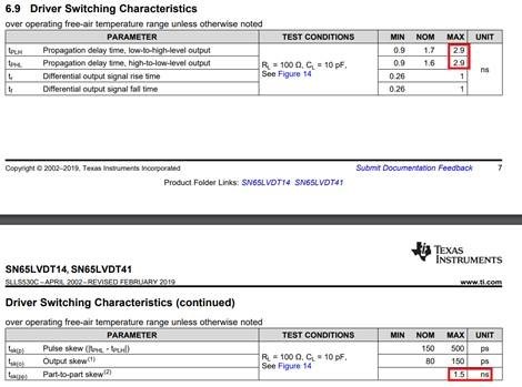
- In the datasheet, a propagation delay-time of max. 2.9 ns is given as well as a part-to-part skew of 1.5 ns. At this point I am interested in the driver propagation delay variance between the individual pins of the same component. Can I assume that it is the following: maximum: 2.9 ns - 1.5 ns = 1.4 ns. Is it correct and if not, how is it? (Because the data sheet advertises a sample rate of 250 MBit/s, I would assume that the variance is less than 2.9 ns between all driver output pins 13 to 20.)
- The SPI transceiver is designed for a supply voltage of 3V3. I have not found a similar component with 1V8 supply. Here you recommend the use of a level shifter. Is that correct (level shifter + transceiver) or do you now also have a 1V8-capable transceiver in your repertoire?
Thanks and Best Regards,
Hans

