This thread has been locked.

If you have a related question, please click the "Ask a related question" button in the top right corner. The newly created question will be automatically linked to this question.

TCAN4550: How to increase the reception of CAN data frames per second

Part Number: TCAN4550

Dear Team,

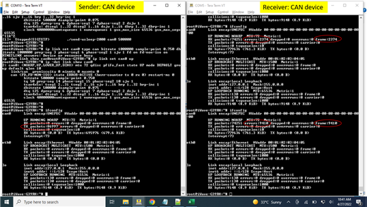
              We are using TCAN4550 module in i.MX8M Mini processor-based hardware with modified tcan4x5x driver of kernel 5.4.70.  We have set below configurations,

              SPI frequency: 18MHz
              Crystal clock frequency: 40MHz
              Bit rate to transfer CAN data: 500kbps

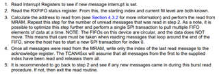
              Currently we are able to receive 150 Frames per second at 500 Kbps using a simulator. Beyond 160 frames per second, we notice the candump application hangs. Frame has 8 bytes of data and payload together has 16 bytes frame.

              We need to test our hardware for receiving 1500 data frames per second from CAN Simulator. CAN Simulator sends 1500 data frames per second. How can I increase the reception of CAN data frames?
              Do I need to increase the RX FIFO 0 and RX FIFO 1 values in mram configuration in dts file?.

Current tcan4x5x configuration in dts file is shown below.

&ecspi3 { 
        fsl,spi-num-chipselects = <1>;
        pinctrl-names = "default";
        pinctrl-0 = <&pinctrl_ecspi3>;
        cs-gpios = <&gpio5 25 GPIO_ACTIVE_LOW>;
        status = "okay";

        tcan4x5x1: tcan4x5x@0 {    
                compatible = "ti,tcan4x5x";
                reg = <0>;
                pinctrl-names = "default";
                #address-cells = <1>;
                #size-cells = <1>;
                interrupt-parent = <&gpio1>;
                interrupts = <15 IRQ_TYPE_LEVEL_LOW>;
                spi-max-frequency = <18000000>;
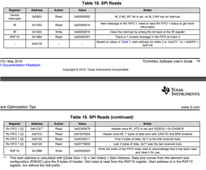
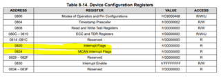
                bosch,mram-cfg = <0x0 3 2 32 10 1 32 7>;
                clocks = <&hclk>, <&cclk>;
                clock-names = "hclk", "cclk";
                data-ready-gpios = <&gpio1 15 GPIO_ACTIVE_HIGH>;
                reset-gpios = <&gpio3 20 GPIO_ACTIVE_HIGH>;
                status = "okay";
        	};
	};

Best Regards,
Aysha T

  • Hi Aysha,

    We have a great app note that goes over how to write software for the TCAN4550. Section 5 actually goes over optimizations to make sending and receiving data more efficient so that you can maximize the performance of your device. I highly recommend following the steps they out lined in section 5 especially 5.3 which goes over bulk reading incoming CAN messages. Essentially you can increase your FIFO size to store multiple incoming CAN message then preform only 1 SPI transaction to read them all in at the same time. This means that your CAN device can be continuously reading incoming messages and storing them in the FIFO. There are some things you have to keep in mind to make sure you don't overwrite data or read in your message incorrectly. So I recommending reading through all of section 5.

    If you have already preformed all of these optimizations then we can talk about what else in your system could be holding you back.

    Best,

    Chris

  • Hi Chris,

    In section 5.1 SPI Transaction Idle Time, it specifies to reduce idle time. Do we need to change any tcan or m_can register setting so that the idle time is reduced and maximum CAN messages are sent?.
    Do you have any reference code to make SPI module support FIFO operation, which allows the user to queue up several words of data at once?

    The section 5.3 specifies bulk data transfer. We are using tcan4x5x driver of kernel 5.4.70. Whether it supports bulk transfer?
    To support bulk transfer, what changes in the driver to be made?

    Best regards,
    AyshaT

  • Aysha,

    What you are reading in 5.1 are best practices on how to write your code so that the SPI's idle time is reduced. There are no settings that you can change to lower your idle time. It is up to how you write your code that reduces your idle time. If you read that section it will walk you through how to write your code for the best SPI efficiency. There is no FIFO operation for the SPI module this is when you would need to do a burst read.

    Once again, the ability to do a bulk transfer will be based on how you write your code. With your current device you should be able to preform a bulk data transfer. Here is the procedure outlined in section 5.3:

    If you follow this procedure you should be able to read in messages with one SPI transaction and then send the index of the last message to the acknowledge register. This will release all the messages that you read. This greatly shortens the amount of time you have to spend writing to the acknowledge register after every SPI read. There is a warning however in section 5.3 so I highly recommend reading through the whole section to make sure that your FIFO does not overflow. This happens while you are reading multiple messages in the FIFO and you haven't sent the acknowledge bit yet. If more messages are coming in your FIFO could start overflowing and your messages could be lost.

    Best,

    Chris

  • Dear Chris,

    What is the maximum data frame received by the CAN device in one second?. What is the size of the frame?
    Is there any reference from you about receiving CAN data 1000 frames per second? What are the configurations of MCAN required to get maximum frame rate? Is there data to provide as a proof?
    Which MCU or MPU is used to test maximum frame rate? What is the speed of the CPU?

    Best regards,
    Aysha T

  • Hi Aysha,

    The number of data frames handled per second by the CAN bus will be dictated by the data rate used and the payload size of each CAN packet. With a configured CAN data rate of 500kbp, assuming the maximum payload size of 64 bytes (CAN FD only), and assuming the worst-case stuff bit (max number of bits per frame), the time for each CAN packet will be nearly 1.4ms. This will result in a maximum frame throughput of around 700 frames per second. 

    To increase this, the data rate of the CAN bus will need to be increased, or the data payload size will need to be decreased. Because the data payload size will likely be dependant on the actual data, it will likely be easier to change the data rate used by the CAN bus. CAN FD allows for the data portion of the frame to use a higher data rate than the arbitration portion. If we increase this data phase data rate to 2Mbps in this example, the CAN packet time decreases to 407us with a corresponding possible throughput of over 2400 frames per second. For information on how to program TCAN4550 for these higher data rates, please see Section 4 of the user's guide linked by Chris  how to write software for the TCAN4550

    Regards,
    Eric Schott

  • Hi Eric,

                     We have configured for RF0N, we are not getting any interrupt when data are sent. We have configured RX FIFO 0 as 64 bytes in MRAM configuration. When the buffer is full we are able to get an interrupt and one byte of data is updated in RX packets of ifconfig.

                     But the interrupt has not happened at the receiver side, for the first byte sent by the sender.

    Best regards,
    Aysha T

  • Hi Aysha,

    What Interrupt are you checking? When you receive a message the M_CAN_INT interrupt flag should be thrown letting you know that the MCAN device has an interrupt. Once you receive this interrupt you should then read the interrupt register 0h1050. This will give you information on where the message is stored and if your RXFIF0 has a new message:

    You say that you have configured for RF0N but what do you mean by this? What steps did you do to configure the device to use RX FIFO 0?

    In the software guide this is the list of commands that we specify for reading one message from the RX FIFO:

    But the interrupt has not happened at the receiver side, for the first byte sent by the sender.

    Just to confirm, when you say this you mean that after you send a message to the TCAN4550 you do not see the interrupt RF0N = 1.

    Best,

    Chris

  • Dear Chris,

            We were sending 8 bytes of CAN data continuously every 2 milliseconds and CAN data were getting received successfully. But sometimes, on receiver side error was detected for a frame and there after all received frames were rejected as error frames as highlighted in the below attached console image. The ifconfig command was used to capture the status.

    To recover from this error condition, CAN link has to be made down and up on the receiver side by giving following command and rerun sending and receiving programs.

           # ifconfig can0 down
           # ip link set can0 type can bitrate 500000 sample-point 0.750 dbitrate 500000 prop-seg 3 phase-seg1 6 phase-seg2 1 sjw 1 fd on fd-non-iso on
           # ip link set can0 up
           # ip -det link show can0

    Why this error situation is happening? How to recover from this error state without link down and up. Since link up and down consumes some time to execute and by that we may loose many frames. Is there any reset or some other methods to recover immediately from error state without losing much frames. Is there register that we have to monitor to check this error state and take action?

    Best regards,
    Aysha T

  • Aysha,

    I'll look through this and get to you on Monday.

    Best,

    Chris

  • Hi Aysha,

    How are you counting these errors, i.e are you reading error frames or are you reading internal registers?

    Do the errors happen randomly across the 86,000 packets or once one error happens it will error out continuously?

    When you say error state is the device entering a different mode other than normal mode, or are you talking about how your device will just start erroring out continuously after one bad frame?

    If you are trying to track the actual CAN message errors there are MCAN registers that you can access that detail what type of error the CAN controller is seeing.

    The interrupt register h=1050 has your protocol error in data phase or arbitration phase bit. You can use these bits to find out if your device is detecting an error in the CAN frame.

    I would recommend waiting for an error and reading your interrupt bits. Let me know what flag is thrown so we can find out what type of error the CAN device is seeing.

    Best,

    Chris