This thread has been locked.

If you have a related question, please click the "Ask a related question" button in the top right corner. The newly created question will be automatically linked to this question.

DP83869EVM: Capable of RJ45 to SFP Data Passthrough?

Part Number: DP83869EVM

Hi all,

I have an DP83869EVM board with the 4 switches in the default position (Normal Operation).

I have an ethernet cable from a packet sending server going to the RJ45 of the DP83869EVM. I also have a 1Gb SFP+ module with an ethernet going back to the receiving server.

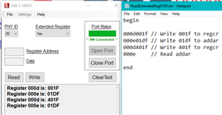
I am able to use the USB MDIO tool to read/write registers, and have been able to to internal loopback successfully, but am wondering if the device is capable of being used as a passthrough?

I am using this as a reference document: https://www.ti.com/lit/ug/snlu237/snlu237.pdf?ts=1650559726305&ref_url=https%253A%252F%252Fwww.ti.com%252Fproduct%252FDP83869HM

Thanks,

George

  • Hi George,

    Yes. This connection is possible. You can use 1G Cu to Fiber mode to make this work.

    Please refer to datasheet section 9.4.2.1 for more details.

    --
    Regards,
    Gokul.

  • Understood. I referred to the datasheet here.
    From 9.4.8.2, I understand I must configure register 0x01DF and then write 0x1140 to register 0x0000.

    My process will be:
    1. Power cycle the board.

    2. Read extended reg 0x1DF to confirm default values (expect 0040):
            Write 001F to reg 0x000D (REGCR)
            Write 01DF to reg 0x000E (ADDAR)
            Write 401F to reg 0x000D (REGCR)
            Read reg 0x000E (ADDAR) -> expect "0040" but getting "01DF"

    3. Write to extended reg 0x01DF:
            Write 001F to reg 0x000D (REGCR)
            Write 01DF to reg 0x000E (ADDAR)
            Write 401F to reg 0x000D (REGCR)
            Write 0041 to reg 0x000E (ADDAR). This sets bit 0 to a '1' instead of '0' to set mode to RGMII to 1000Base-X. Bit 6 on by default.

    4. Read extended reg 0x1DF to confirm changes were made:
            Write 001F to reg 0x000D (REGCR)
            Write 01DF to reg 0x000E (ADDAR)
            Write 401F to reg 0x000D (REGCR)
            Read reg 0x000E (ADDAR) and confirm "0x0041"

    5. Write 0x1140 to reg 0x0000.

    I am getting stuck on step 2. I don't believe my extended register access is working properly.

    I'm reading "0x01DF" from ADDAR but I expect "0x0040" (the default value of register 0x01DF).

    Thanks,

    George

  • Hi George,

    Can you please try the same register sequence with 'Extended Register' drop down in the USB2MDIO tool set to 'No'?

    --
    Regards,
    Gokul.

  • Hi Gokul,

    The same register sequence with 'Extended Register' set to 'No' is as follows:

    Register 000d is: 001F
    Register 000e is: 01DF
    Register 000d is: 401F
    Register 000e is: 0000 // this is now '0000' instead of '01DF'

  • Hi George,

    Can you please check registers other than 1DF in the extended domain? In the non-extended domain, can you please check if the other registers are giving out the proper values?

    --
    Regards,
    Gokul.

  • Hi Gokul,

    I have a script to read non-extended registers, which works properly:

    RegRd.txt file is open...
    Register 0000 is: 1140
    Register 0001 is: 796D
    Register 0002 is: 2000
    Register 0003 is: A0F1
    Register 0004 is: 01E1
    Register 0005 is: CD01
    Register 0006 is: 006F
    Register 0007 is: 2001
    Register 0008 is: 4000
    Register 0009 is: 0300
    Register 000A is: 3800
    Register 000B is: 0000
    Register 000C is: 0000
    Register 000D is: 401F
    Register 000E is: 0000
    Register 000F is: F000
    Register 0010 is: 5048
    Register 0011 is: BF02
    Register 0012 is: 0000
    Register 0013 is: 1C42
    Register 0014 is: 29C7
    Register 0015 is: 0000
    Register 0016 is: 0000
    Register 0017 is: 0040
    Register 0018 is: 6150
    Register 0019 is: 4444
    Register 001A is: 0002
    Register 001B is: 0000
    Register 001C is: 0000
    Register 001D is: 0000
    Register 001E is: 0012
    Register 001F is: 0000
    End of file.

    I attempted to read extended register 0x0032 and received the same behavior (addar data = extended register address instead of the data at the extended register address).

    Register 000d is: 001F // write 001f to 000d
    Register 000e is: 0032 // write 0032 to 000e
    Register 000d is: 401F // write 401f to 000d
    Register 000e is: 0032 // read 000e

  • Hi George,

    When accessing registers through 0x000D and 0x000E, the drop down of Extended register should always be set to 'No'. Incase you want to access the extended register directly (by using it's address directly and not through 0x000D and 0x000E), you will have to set the drop-down to Yes.

    Can you please check if you can program the value 0x0004 into register 0x01DF?
    After programming this, you can follow the section 9.4.8.4 (not 9.4.8.2) (because you are looking for Copper to Fiber mode)

    --
    Regards,
    Gokul.

  • Hi Gokul,

    I tried with the dropdown set to "No" and it seems to have worked. Perhaps I missed it in my earlier response.

    My next question concerns the datasheet. I believe there is a typo in section 9.4.8.4. It reads as follows:

    I see a stray "9" in the last bullet. Should I disregard? Or does it mean to say:

    • Write 0x0B00 to register 0x0009?

    I see this in some of the other register configuration steps for auto-negotiation advertisement and master/slave settings. I also noticed a write of "0x0B00" would set the device to configure as master but also disable Master/Slave configuration.

  • Hi George,

    I think it's just a typo. You need not program 0x0009.

    --
    Regards,
    Gokul.

  • Hi Gokul,

    I was able to achieve passthrough after following the sequence in 9.4.8.4 - I did not program 0x0009.

    Thank you for being so responsive.

    George