This thread has been locked.

If you have a related question, please click the "Ask a related question" button in the top right corner. The newly created question will be automatically linked to this question.

TPS65987EVM: Battery Status Data Objects (BSDO) Registers

Part Number: TPS65987EVM

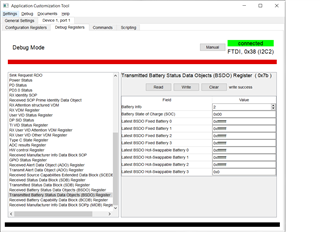
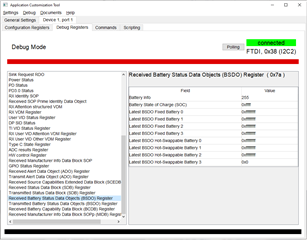
When running the TPS6598x Application Customization Tool (version 6.1.1 or version 6.1.3), in debug mode and under the Debug Register tab, there are two registers called; Received Battery Status Data Objects (BSDO) Register (0x7a) and Transmitted Battery Status Data Objects (BSDO) Register (0x7b).  Does anyone have any more understanding regarding these registers?  There is a field in these registers named Battery State of Charge (SOC), and I am wondering how that works.

Questions:

1. What is sensing the State of Charge and then filling in the SOC field?  Is it an external uProc connected to the i2c bus that writes the information directly into the TPS65987DDH using a 4CC command?

2. I have two TPS65987EVM boards connected together (over the USB cable connectors) and the two boards are able to negotiate a PD contract between themselves, but I am not able to "pass across" the SOC field between these two ICs.  Has anyone out there tried to do the same experiment?  It seems like it should be an easy task, but I've tried a bunch of sequences and nothing is working for me.

  • Hi, 

    I'll get back to you on Monday.

    Thanks
    Prajith

  • Hi John,

    1. What is sensing the State of Charge and then filling in the SOC field?  Is it an external uProc connected to the i2c bus that writes the information directly into the TPS65987DDH using a 4CC command?

    You are right, EC need to sense SOC and update the register using 4CC command. 

    2. I have two TPS65987EVM boards connected together (over the USB cable connectors) and the two boards are able to negotiate a PD contract between themselves, but I am not able to "pass across" the SOC field between these two ICs.  Has anyone out there tried to do the same experiment?  It seems like it should be an easy task, but I've tried a bunch of sequences and nothing is working for me.

    Could you share I2C trace ?

    Thanks
    Prajith

  • Hi Prajith.  Thank you for trying to help me.

    I don't have a i2c trace to share with you, but I can tell you what I am doing...

     1. I am using the TPS65987EVM boards with the TPS6598x Application Customization Tool (version 6.1.1 or version 6.1.3) in Debug mode.  I have one TPS65987EVM connected to a laptop and another one connected to a desktop computer.

    2. It is my understanding that the battery normally resides on the sink side of the USB-C cable.  So, I have one TPS65987EVM getting power from the 19V connector (Source) and the other TPS65987EVM being the sink.  I connect the USB-C cable between the EVM boards and I observe that the source EVM has illuminated the 20V LED, meaning it is sourcing 20V.  After the power contract has become active, then I connect the TPS65987EVM to the computer via the USB-micro connection.

    3. On the EVM that is the sink, I type in a battery "2" and I give it a charge value of "0x00ff".  Then, I click the write button.  It comes back and says it was "write success".  Note, I have this panel in "Manual" mode.  If I run the Debug tool in "Polling" mode, any changes to this panel does not take.  Instead, the battery will reset to "255" and the State of Charge will go to "0xffff" after about 2 seconds.

    4. Then, on the EVM that is the source, I go to the Debug Commands panel and select [GBaS], Get Battery Status.  I click the button "Execute GBaS".  It returns SUCCESS_CMD.

    5.Then, I go to the Debug Registers tab and select the Transmitted Battery Status Data Objects (BSDO) Register and look at the information.  The data there is the default values of batteryInfo "255" and Battery State of Charge (SOC) "0xffff".  The values have not changed.

    I feel like maybe I don't understand how the battery SOC feature is supposed to operate in USB-PD, or I am using the TPS6598x Application Customization Tool improperly.  Perhaps TI can tell me how they tested the TPS65987D to see if this capability was properly implemented in the base file.  That information might reveal what I am doing wrong.

  • Hi John,

    I'll take a look at it tomorrow.

    Thanks

    Prajith

  • Hi John,

    I successfully tested GBaS command on 88DH with 992AE as far-end. May I know more about your end-application? if 88DH is supposed to respond to or initiate GBas command? 

    Thanks
    Prajith 

  • Hi Prajith,

    I don't exactly know what you are saying...  What is a 992AE?  I'm guessing 88DH is the TPS65988DH.  When you are testing the GBaS command, are you using the TPS65981_2_6_7_8 Application Customization 6.1.3 customization application to do the experiment?

    JohnK

  • John, 

    992AE is another PD controller which I used as far-end here. Do you know if the end applicaiton you are working on is expected to issue GBas or respond to GBas? 

    Thanks
    Prajith 

  • Hi John,

    I tested it using two 88DH EVM and GBaS command works fine. Please find the screenshots below. 

    Also, please check if you are Vconn provider. 

    Thanks
    Prajith