This thread has been locked.

If you have a related question, please click the "Ask a related question" button in the top right corner. The newly created question will be automatically linked to this question.

DS250DF230:Register setting about 2x2 Cross-Point

Part Number: DS250DF230


Hello, TEAM.

Our customer  would like to use the 2x2 Cross-Point and know about setting of register.

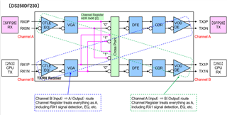
How do we set the 2x2 crosspoint?
Does it register Channel A and Channel B alternately, or register at the same time where it needs to be set at the same time?

Also, front port input configuration and front port output configuration
Is it necessary to do it at the same time?

Best Regards,

  • Hi,

    These details can be found in the programming guide for this device.  You can request access to this programming guide at the link below.  Please let us know if you encounter difficulties implementing the procedures in the programming guide.

    https://www.ti.com/drr/opn/DS250DF230-DESIGN 

    Thanks,
    Drew

  • Thank you for your reply.
    Customers want to check the user's guide on the assumption that the 2x2 crosspoint configuration is set first.

    When setting the front port input configuration, the output is Channel B on input Channel A.

    STEP 4 to STEP 7 of the device configuration setting table are set by the Register of Channel A.
    For STEP 8 to STEP 15, switch to Channel B and set the register. Or STEP 4 to STEP 6 are set together with Channel A / B.
    Switch to Channel A only and set the STEP 7 register.
    Switch to Channel B only and set the registers of STEP 8 to STEP 15.
    Channel A / B Set STEP 16 registers at the same time.

    Our customers want to know whether to set Channel A and Channel B alternately, or to set the registers at the same time where they need to be set at the same time, or how to set them in the case of a crosspoint configuration.

    In addition, the front port input configuration and front port output configuration
    Please tell me if it is necessary to do it at the same time.

    Is it possible to show how to set it concretely in the device configuration setting table?

  • Hi,

    I would not expect any device issues caused by setting all of CHA and then all of CHB, even in a crosspoint configuration.  If there are any concerns, I would recommend disabling the device output while going through configuration steps.  This could be done through a couple methods.

    1) Hold CHA and CHB in CDR reset until everything is configured appropriately.

    2) Temporarily set output to mute while device channels are being configured.  This can be done by setting 0xA5=[111] and 0x09[5]=1.

    Thanks,
    Drew

  • Sorry again.

    Crosspoint configuration settings
    (1) Input RX0 (Channel A) ⇒ Output TX1 (Channel B)
    The green dotted route in the figure
    (2) Input RX1 (Channel B) ⇒ Output TX0 (Channel A)
    The blue dotted route in the figure

    Our customer says

    (1), (2), How Channel Register A and B handle each route?

    For example, register settings, concern, important point.

    Best regards.

  • Hi,

    For Input RX0 --> Output TX1 (The green dotted route), CTLE and VGA settings are controlled by CHA registers.  DFE, CDR, VOD, and DE settings are controlled by CHB registers.

    The opposite holds true for RX1 --> TX0.

    Thanks,
    Drew