This thread has been locked.

If you have a related question, please click the "Ask a related question" button in the top right corner. The newly created question will be automatically linked to this question.

DS90UB953-Q1: how to understand pixel ability, video aggregation throughput, CSI bandwidth, line rate?

Part Number: DS90UB953-Q1

Hi.

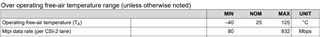
I found difficulty when I try to understand those concepts as title. let me take 953 as example. we can get that from datasheet as below:

 here is my questions:

  1. when we talked about video aggregation size, are we talking CSI bandwidth? like for 953, the maximum video aggregation side is 832M*4=3.33Gbps, right?
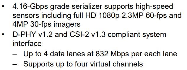
  2. when we talked about what kind of imager device can support, are we also limited by video aggregation size/CSI bandwidth? from the datasheet, the long packet CSI-2 has 40bit per frame. so for 2.3MP 60fps imager, it need 2.3M*60*40=5.5Gbps without blanking which is beyond 3.33G or 4.16Gbps. where is wrong?
  3. when we talked about 4.16Gbps, are we talking the FPDLINK3 forward channel line rate? from the table as below, why the FC data rate is always larger than CSI bandwidth?
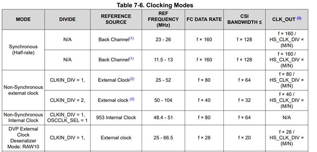
thank you!

B&R

Yuan

  • Hello Yuan,

    1. The 953 serializer can send Forward Channel (FC) data (SER->DES) at a rate of up to 4.16Gbps, depending on its reference clock source. If you are in Synchronous mode and the REFCLK is 26MHz, then the FC rate will be 4.16Gbps. The FC contains video data as well as GPIO, I2C, encoding, error detection bits, etc... Of the 4.16Gbps FC data, up to 3.328Gbps of that will be the video data received at the CSI-2 receiver on the serializer. This means that it is possible to transfer up to 3.328Gbps (26MHz x 128) of video data over the FC link.
      1. There are x4 DPHY data lanes and each data lane can accept up to 832Mbps of video data.
      2. If you use a lower reference clock, then your CSI Output Bandwidth will be reduced. You will lose data if your input bandwidth is greater than your output bandwidth.
    2. The 953 can support up to 3.328Gbps of video throughput, if the appropriate reference clock is used and all four CSI-2 lanes run at the max 832Mbps rate. 
      1. Use the below equation to calculate the video throughput of the imager. If the video throughput is less than the "CSI Bandwidth" of your 953's configuration, then the 953 serializer can support your imager.
      2. Video Throughput = HActive x VActive x (Frame Rate) x Bits-Per-Pixel x Overhead(Assume 25% if unknown)
    3. FPD-Link III Forward Channel line rate contains video data as well as information for GPIO, I2C, encoding, etc... Video data takes up a majority of the FC bandwidth, which is calculated using the equations under "CSI Bandwidth" in Table 7-6, but the FC also includes other information as well, which is why FC rate is higher than the CSI Bandwidth.

    Best,

    Justin Phan

  • thank you!

    • Use the below equation to calculate the video throughput of the imager. If the video throughput is less than the "CSI Bandwidth" of your 953's configuration, then the 953 serializer can support your imager.
    • Video Throughput = HActive x VActive x (Frame Rate) x Bits-Per-Pixel x Overhead(Assume 25% if unknown)

    from datasheet the 953 can support 2.3MP, 60fps, using the equation, Video throughput=2.3MP*60*BPP(I don't know exact,  use 32b from datasheet)*125%=5.52Gbps, which is beyond CSI bandwidth. where is wrong?

  • Hello Yuan,

    The 953 can actually support a total of 3.328Gbps of Video Throughput. The CSI-2 receiver port can support up to four CSI-2 data lanes and each data lane supports up to 832Mbps of video throughput. If you route all four CSI-2 data lanes to the camera/imager, then the total amount of video data that the 953 can support is (4 x 832Mbps) = 3.328Gbps.

    The customer is supposed to use the video throughput equation to calculate the video throughput of their camera/imager and to verify that it is less than 3.328Gbps (if all four CSI-2 data lanes are used).

    Check the camera/imager datasheet and use the values for your desired camera configuration in this equation:

    Video Throughput = HActive x VActive x (Frame Rate) x Bits-Per-Pixel x Overhead(Assume 25% if unknown)

    Best,

    Justin Phan

  • hi,

    I totally understand your point and my question is:

    from datasheet the 953 can support 2.3MP, 60fps imager, using the equation, Video throughput=2.3MP*60*BPP(I don't know exact,  use 32b from datasheet)*125%=5.52Gbps, which is beyond CSI bandwidth(3.328Gbps). for my calculation, where is wrong?

  • Hello Yuan,

    The use of the term "2.3MP/60fps" in the datasheet is more of a Marketing decision, since most customers recognize terms such as "Mega-Pixel Resolution" and "FPS" instead of 3.328Gbps Video Throughput.

    But our serializers can actually support much higher resolutions if other camera configurations such as FPS and BPP are lowered. The opposite is true as well, where we can support much higher FPS or BPP if the resolution is lowered.

    A more accurate representation of the technical limits of the 953 device is the Video Throughput limitation. You would use the equation I gave to calculate the Total Video Throughput of the connected camera/imager and then check to see if it is within the technical limitations of the 953 part (832Mbps per lane and up to 4 MIPI CSI-4 data lanes).

    The "2.3MP/60fps" used in the datasheet title is more of a rough example. You need to use the parameters from your own camera setup in the equation.

    Best,

    Justin Phan

  • Justin,

    thank you!

    And I also have question about the synchronization.

    for multi-sensor in synchronization, how the part make it, through framesync? the precondition for framesync is that all 953 with 960 were set in sync mode, right?

    thank you!

  • Hello Yuan,

    The FPD-Link devices support multi-sensor synchronization in any mode. You do not need to set the 953/960 to Synchronous Mode before enabling multi-sensor synchronization. 

    The 960 device can support internal and external Framesync operation. In internal Framesync operation, a pulse is sent to one of the GPIO pins on each connected serializer, which can sync the frames of multiple cameras. The pulse period is controlled through the register settings in the 960. In external Framesync operation, an external device such as the SoC will feed a pulse signal into the 960 GPIO pin. The 960 will then propagate that signal to one of the GPIO pins in the connected serializers.

    See Section 7.4.24.2 Internally Generated FrameSync in the 960 datasheet for more information on using the internal Framesync functionality.

    Best,

    Justin Phan

  • hi Justin, 

    Thank you. still curious, if it's in framesync operation, where the 953 clock comes from? it can only comes from 960 in synchronization mode, or it can also comes from external clock in? I have this question from the picture as below:

    and also want to know how to generate a clock for the image sensor? I mean from the 953 datasheet table7-6 as below, we can know the CSI bandwidth should be lower than f*128. but what the clock source for it? 

    thanks!

  • Hello Yuan,

    This image is pulled from one of the FPD-Link training videos. In the video, it states that each camera may have a different oscillator, which may run at a slightly different frequency an cause the video streams to be slightly disjointed when they are aggregates at the processor.

    If you run each device in Non-Synchronous Mode, then each Serializer PCB board will have a separate oscillator, which will each operate at slightly different frequencies, due to individual parts differences. If you are using the CLK_OUT pin on the SER as a reference clock to the camera, then there will be slight differences in the reference frequency applied to each camera. This will result in slightly unsynchronized video being sent into the processor, which will force the user to use extra processing power to stitch all of the video together.

    In this scenario, you could send a FrameSync signal from the Processor to each of the cameras to synchronize the video. Many camera sensors have a dedicated sync line, which can be used to indicate the exact moment a frame should be taken. Our 960 DES device can propogate the same FrameSync signal to all of its connected serializers, with limited skew that will not be significant in the overall system.

    If you run each device in Synchronous Mode, then the single reference oscillator used on the 960 will be used as the reference clock for all of the connected serializers and cameras. The same reference clock signal will be sent over the Back Channel to each of the connected serializers, with limited skew. This will result in all of the connected cameras and serializers to operate on the same reference clock signal and results in more synchronized video from all connected cameras. In Synchronous mode, you can still send a FrameSync signal to connected cameras to synchronize the frames of multiple cameras.

    In summary, if multiple oscillator parts are used in the system, then FrameSync signals should be sent to each camera to synchronize the video and reduce the work that the processor has to do. If you have a system where everything is running on a single central oscillator part, then everything will run on the same clock and the FrameSync signal might not be necessary. But that ultimately depends on the specs of the oscillator used and will need to be verified in the customer system.

    Best,

    Justin Phan

  • Hi Justin,

    thank you! very clear!