This thread has been locked.

If you have a related question, please click the "Ask a related question" button in the top right corner. The newly created question will be automatically linked to this question.

DS90UB954-Q1: Margin Analysis fails on Strobe Position in the Middle of the Eye

Part Number: DS90UB954-Q1
Other Parts Discussed in Thread: ALP,

Hello TI-Forum,

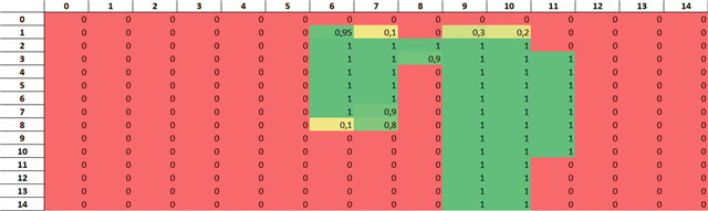
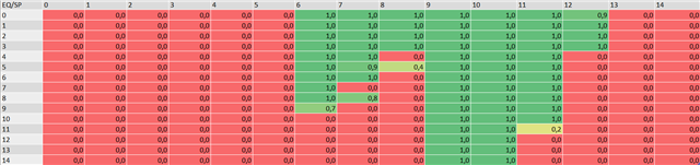
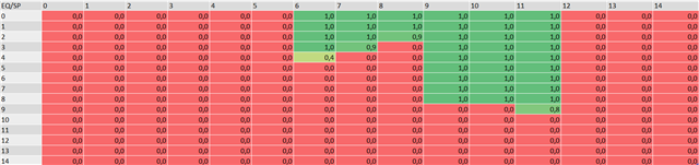
we have a persistent occurrence, that the overall margin analysis looks good, but strobe position 8 is very bad, even though the surrounding stobe positions have many equalizer levels that pass. 
I've had a look at CML-OUT at different EQ-levels, and both the eye and the general waveform look normal (no sudden cave ins, especially not in the middle). I could not find any indication as to why strobe position 8 would produce errors for most equalizer levels, when 6, 7, 9, 10 and 11 don't.

Of coure it is possible that the error is frequent enough for the SP to fail the margin analysis, but not so frequent that I would see it with a casual glance at the waveform/eye.

Example 15m cable:

These would probably be a stable connection for a 15m cable, but doesn't pass the criteria from the Margin Analysis Application Report, because of strobe position 8.
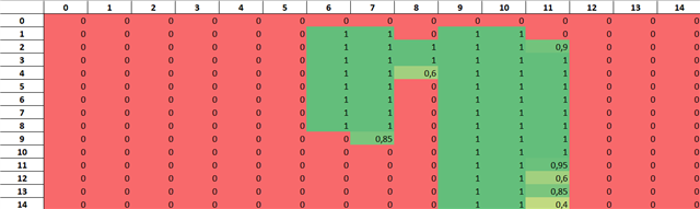
Example 5m cable:

(The varying margin analysis plots for each cable come from the varying current on the coaxial cable)

Also: It is shown in the Margin Analysis Application Report that strobe position 14 corresponds to the leftmost part of the eye and 0 to the rightmost. The way the data is shown in the GUI (ALP) and what is exported as CSV goes from 0 to 14 so it essentially flips the eye. I think it would be nicer and more intuitive to display the strobe positions the other way around.

Kind regards,

Teresa Fehr

  • Teresa,

    These results look quite normal actually. See the Margin Analysis Program app note SNLA301 for examples. The working strobe positions always fall in the strobe 9-10 range which is why the DS90UB954-Q1 datasheet recommends setting 0x41 = 0xA9. If you set the strobe min/max to 9-10 positions you will always adapt to a strong portion of the MAP. 

    The MAP is not actually an "eye diagram" per say. It is showing the relationship between the sampler and the data bit UI which is why the MAP is "flipped" as you say. 

    Best Regards,

    Casey 

  • Hello Casey,

    yes, no question about chosing 9 or 10 as strobe positions. I was just wondering why for a lot of EQ-levels ONLY strobe position 8 is not passing (e.g. first MAP example EQ-level 4: SP 5 and 6 pass, 8 does not, then 9, 10, 11 pass). I'm aware that this is not an eye, but the error free strobe positions at least indicate how wide the eye of the equalizer output is (or do they not?). If SP 6 and 7 pass, I would assume the eye is open enough at those positions, same for 9, 10 and 11.

    I guess my question is: What could lead to errors here? As I said, I have not seen waveforms where the middle of the UI is caved in, when looking at different EQ-levels, just an increase in ISI/jitter. If SP 8 and 9 are advised, then is this just a property of the DS90UB954-Q1? 

    Kind regards,

    Teresa

  • Hi Teresa, 

    It is possible the certain reflections at specific frequencies could cause a portion of the eye to be pinched which may result in what you are seeing above.  However, as long as you can get a large enough group of settings for the receiver then it will be able to adapt as needed.

    Regards,

    Nick