This thread has been locked.

If you have a related question, please click the "Ask a related question" button in the top right corner. The newly created question will be automatically linked to this question.

DS90UB936-Q1: 0x6E, 0x6F; GPIO mapping

Part Number: DS90UB936-Q1

Hi, Team,

    Our setup is 935 + 936, and we plan to use 3 GPIOs  from host to control ub935 GPIO output via ub936.

    One of our GPIO design is 

     host GPIO6 ->  ub936 GPIO6 -> ub935 GPIO0

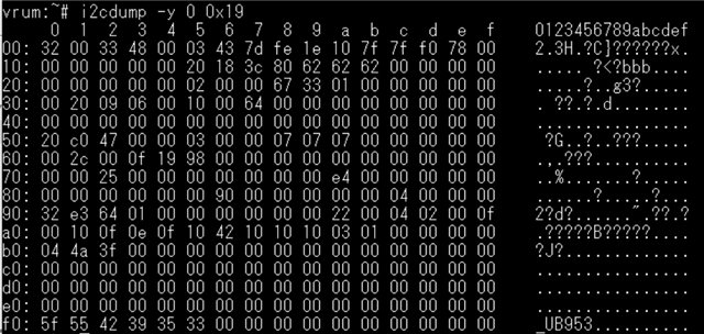
    Some related configure in below.


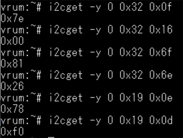
    When we set host GPIO6 to 1, then ub936 GPIO6 state is 1

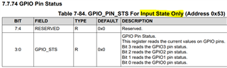
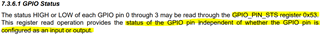
    But UB935 side GPIO0 still is 0.

   Why UB935 GPIO_0 can't be set to 1?

Thank you,

--Blake


  • Hello Blake,

    It seems you want to send a signal over the Back Channel, from Host -> GPIO6 (936) -> GPIO0 (935). It is possible to map GPIO6 on the 936 DES to GPIO0 on GPIO0 on the 935.

    Here is an example on how to set the registers, assuming the 935 is connected to RX Port 0 on the 936:

    936:

    reg 0x0F = 0x40  // Set 0x0F[6] = 1 to enable GPIO6 as an input, every other GPIO is input disabled

    reg 0x16 = 0x00  // Make sure to disable output on the GPIO6 pin

    reg 0x4C = 0x01  // Enable writes to Port 0 registers

    reg 0x6E = 0x86  // Map GPIO6 to BC Slot 0 at RX Port 0

    935 (RX Port 0):

    reg 0x0D = 0x10  // Set output source of GPIO0 to BC Slot 0 in the connected remote deserializer

    reg 0x0E = 0x1E  // Enable GPIO0 output

    Best,

    Justin Phan

  • Hi, Justin,

          Thank you for the reply.

          As confirm with you list related REG setting, I believe my current setting is correct.

          UB936:

             REG(0x0F) = 0x7e  // bit 6 = 1 enable GPIO6 as an input.

             REG(0x16) = 0x00 // disable GPIO6 output function.

             REG(0x4c) = 0x01 // Enable write to port 0

             REG(0x6e) = 0x26 // bit[0:3] Mapping GPIO6 to BC slot 0 at RX port 0

          UB935:

              REG(0x0d)= 0xf0 // Output source of GPIO0(bit 4) to BC slot 0 in the connected remote deserializer

               REG(0x0e)= 0x78 // Enable GPIO0 output(bit4) and disable GPIO0 input(bit 0)

           But it still exist the issue I reported in 1st message, that is outsider GPIO rise to high and UB936 GPIO6 state can be observed to 1 but UB935's GPIO 0 still is 0.

           Have other factor would make this issue? No matter HW or SW configure.

    Thank you,

    --Blake

  • Hello Blake,

    I tested the code that I shared with you on our EVMs and it does work as intended. Software should not be an issue. Are you testing this GPIO setup using EVMs or a custom PCB?

    Best,

    Justin Phan

  • Hi, Justin,

        I have no EVM for testing and I'm testing with our custom  PCB.

    Thank you,

    --Blake

  • Hello Blake,

    I also tried your register settings on the EVMs and can confirm that the software register settings are correct. If you write the registers in the order that you wrote in your post, then the GPIO mapping should work. If you apply a HIGH signal to GPIO6 on the 936, then GPIO0 will also go HIGH on the 935.

    1. Are you able to confirm through local and remote I2C reads that all of the registers have been correctly written on the 936 and 935 devices? 
      1. Maybe an I2C write command got lost somehow?
    2. Is there anything connected to GPIO0 on the 935, that could be pulling the signal LOW?
      1. Check the schematic and maybe probe around to see if an LED broke or if there is an accidental short to ground?

    Best,

    Justin Phan

  • Hi, Justin,

          About i2c write command got lost possibility, I think it should be impossible. Because current our video streaming is working, and we have let several i2c devices working properly at ub935 side.

         The 4 GPIO of ub935 were wired to a device's SPI interface, and we plan to use it to transfer SPI signal. Since I found the host output clock can't transfer to UB935 side, so I have change host side SPI pin to generic GPIO for testing this issue firstly.

    Thank you,

    --Blake

  • Hi Blake,

    If you are streaming video from the SER->DES, then that means the Forward Channel is working. But it is possible that the Back Channel may not be working if the BC rate on the SER/DES are not configured correctly. This is easy to check. Just send a remote I2C read command from the Processor->DES->SER and read some known register value on the 935 SER. If the result is correct and not 0, then that means the Back Channel communication (DES->SER) is working. 

    If you can confirm that the 936 and 935 have all of the registers written to the expected values, then I would suspect that GPIO0 on the SER is shorted to ground.

    Best,

    Justin Phan

  • Hi, Justin,

         Okay, got it.
      I just check UB935 REG 0x0 to get SER ID and it's correct as we expected 0x32.

         How do I confirm the back channel is working properly? Below dump data from UB935, could you help to check has any back channel related setting incorrect?

    Thank you for the help.

    --Blake

  • Hello Blake,

    If you can properly send a remote I2C read command from the Processor->DES->SER and read a correct register value from the 953, then your Back Channel is working.

    I also did a few more tests on an EVM setup. In your setup, you are reading register 0x53 on the 953 in order to view the status of GPIO0 on the 953. This register will only show the status of the GPIO pins on the 953 if the GPIO pins are configured as inputs. In your setup, GPIO0 is configured as an output, so register 0x53 will not show the state of the GPIO0 pin. It is expected for register 0x53=0x00 in your setup.


    I see where the confusion is though, since the datasheet specifies that this register can be used to read the GPIO status, regardless of how the GPIO pin is configured. 

    This description is wrong. I tested using EVMs. Here is the configuration you provided and what I tested on the EVMs:

          UB936:

             REG(0x0F) = 0x7e  // bit 6 = 1 enable GPIO6 as an input.

             REG(0x16) = 0x00 // disable GPIO6 output function.

             REG(0x4c) = 0x01 // Enable write to port 0

             REG(0x6e) = 0x26 // bit[0:3] Mapping GPIO6 to BC slot 0 at RX port 0

          UB935:

              REG(0x0d)= 0xf0 // Output source of GPIO0(bit 4) to BC slot 0 in the connected remote deserializer

               REG(0x0e)= 0x78 // Enable GPIO0 output(bit4) and disable GPIO0 input(bit 0)

    When you apply a HIGH signal to GPIO6 on the 936, then the GPIO0 pin on the connected 935 will go HIGH. I verified this by using a DMM to probe GPIO0 on the 953/935 EVM. Reading register 0x53 on the 953 cannot be used to determine the status of the GPIO0 pin on the 935.

    Your script is correct and can only be confirmed by probing GPIO0 on the serializer with a multimeter.

    I will submit a request to correct this sentence in the next revision of the 953 datasheet.

    Best,

    Justin Phan 

  • Hi, Justin,

          Thank you for clarify my question.

          I really be confused by the UB935 0x53 register, and we could probe the level change on 935 GPIO pin now.

    Best regards,

    --Blake