Part Number: TUSB8020B
Hi Team,
We have many following questions related with TUSB8020B. Could you please answer them?
1. IBIS Model : usb2_HS_R / usb2_HS_RC
We can find the two models of USB2.0 High speed mode, usb2_HS_R and usb2_HS_RC. What is different?
In other words, What does "recommended C load of 1pF" mean?
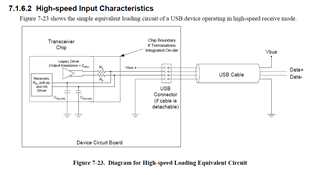
| USB 2.0 High Speed mode, for DP pin 240MHz (Internal Termination ON) with
| recommended C load of 1pF.
2. IBIS model : C_comp on usb2_HS_R / usb2_HS_RC
My customer simulates his board with IBIS model. However, he doubts too C_comp value (around 6pF). He thinks C_comp is usually <1pF on other devices (such as I2C pin etc.). Please let us know your comments.
3. Iozp condition
On the TUSB8020B datasheet P.7, we can see the following.

My understanding is "MAX Iozp is max current value from pin to external while Input voltage moves from 0V to VDD33 (3.3V)." Is it correct? Please let us know.
4. Internal PU/PD resister value
Could you please let us know the internal PU/PD resister value?
5. External Pull-up/Pull-down resister value.
On the datasheet P.26,27, 4.7kohm resisters are used on the following pins.
GANGED / SMBA2 / HS_UP : 4.7kohm external pull-down
FULLPWRMGMTZ / SMBA1 / SS_UP : 4.7kohm external pull-down
PWRCTL1 / BATEN1 : 4.7kohm external pull-up
PWRCTL2 / BATEN2 : 4.7kohm external pull-up
Does TI recommend 4.7kohm value related with the above pins? Please let us know.
Thanks and best regards,
M.HATTORI.