This thread has been locked.

If you have a related question, please click the "Ask a related question" button in the top right corner. The newly created question will be automatically linked to this question.

TCAN1044-Q1: Calculate the loss of TCAN1044-Q1

Part Number: TCAN1044-Q1

Hi Team

We would like to calculate the loss of TCAN1044 , (1)Normal mode (2) Low power standby mode (3) Max power loss !

Could you share the calculation formulas ?THX

The calculations I know are roughly as follows, but I need your help to confirm 

1. Normal mode

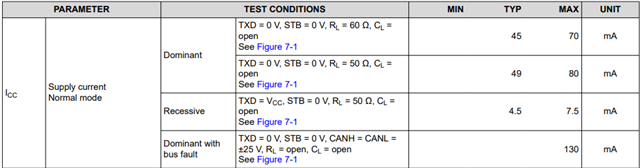
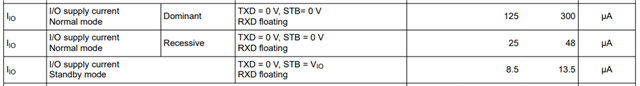
(45mA * 5V(Vcc)) + (5V(Vio) * 125uA(Io))= 225.6mW

2.Low power standby mode

(1uA * 5V(Vcc)) + (5V(Vio) * 8.5uA(Io))= 47.5uW

3. Max power loss

(70mA * 5V(Vcc)) + (5V(Vio) * 300uA(Io))= 351.5mW

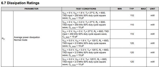
4.Does the value below belong to Normal mode? It's a bit different from my calculation ,THX

  • Hi Team

    Share the SCH with you ,THX

  • Hi Kygo,

    1. The power considerations for Normal mode follow the values you use here with one additional consideration: Dominant power draw is only present during '0' bits. For all times when the driver is idle or transmitting a log '1', the current draw will be the recessive value (7.5mA max). Assuming that the transceiver is not idle and is constantly driving data and with a balanced packet containing 50% dominant*, the final value will be much closer to the listed average power dissipation table.

    Pnorm: [(Idom * Vcc) * %dom] + [(Irec * Vcc) * (1 - %dom)] = [(45mA * 5.0V) * 0.5] + [(4.5mA * 5.0V) * (1 - 0.5)] ~= 124mW

    * The actual %dom time depends on the whole CAN frame, not just the data that is being sent. Because of the number of bits that are not dependant on the data, the %dom time will most often be in favor of the recessive state (i.e. %dom < 50%).

    2. The Standby calculations are correct. Keep in mind that Vcc can be removed in this mode as the low-power receiver is powered by the Vio supply.

    3. The max peak power used by the transceiver will be in the case of a bus fault with the driver current limit reached. This power will only persist until the CAN controller has recognized that communication is not possible and CAN traffic is stopped. This time is too short to impact most thermal concerns and should not be used to estimate long-term power consumption. 

    Pbusfault: (Ibusfault * Vcc) = 130mA * 5.5V = 715mW. 

    4. See 1 for explanation of how %dom impacts normal mode power consumption.

    Lastly, I'll mention that if these considerations are being done for thermal characteristics, keep in mind that a lot of the dominant-state power is being dissipated by the termination resistance between CANH and CANL. The transceiver IC only dissipates power from the voltage drop across the driver and the quiescent current used by the device itself. 

    The schematic here looks good and I don't have any major changes to recommend. Let me know if more detailed comments would be needed here.

    Let me know if you have any more questions.

    Regards,
    Eric Schott