This thread has been locked.

If you have a related question, please click the "Ask a related question" button in the top right corner. The newly created question will be automatically linked to this question.

DS90UB954-Q1: DS90UB954-Q1 TO DS90UB953-Q1 BCC I2C ERRORS

Part Number: DS90UB954-Q1
Other Parts Discussed in Thread: ALP

I originally posted the following comment in the thread below, but was asked to make a new topic.  Some of the syntax is referencing the previous thread.

https://e2e.ti.com/support/interface-group/interface/f/interface-forum/1091935/ds90ub914a-q1-fpd-linkiii-with-ds90ub914a-q1-and-ds90ub913a-q1/4080683?tisearch=e2e-sitesearch&keymatch=DS90UB914A-Q1%3A%20FPD-Link%E2%85%A2%20with%20ds90ub914a-q1%20and%20ds90ub913a-q1#4080683

I am experiencing a very similar problem with the DS90UB954 & DS90UB953 link.
I have not been able to determine why it happens yet, but it is not associated with address or register offset.
I do not know what the default BCC timeout is for your parts, but on on the 954/953 setup it is 254msec.

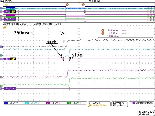
The upper portion of the initial scope capture shows the ISP to 954 waveform of a successful boot process.  The bottom portion of the same image shows a failed waveform where the 954 did not produce an ack for the ISP's I2c write to the sensor.  The time between points A & B is roughly 250msec which is the default value of the 954 BCC timeout. 

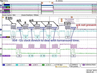
The next scope capture shows a closeup of the beginning of a failed write (point a in the upper part of the capture).  You can see a good write cycle consisting of a 7bit (write) address, 16bit register offset, and 8bit data.  For each 8bit cycle you see the acks present after the clock stretch which happens while waiting for the 953 & sensor to finish.  In the address portion of the next 4 byte write cycle the 954 does not produce the required ack to the ISP, but you can see that the ack "was produced" by the sensor to the 953.  

The final scope capture shows a closeup of the end of the same failed write cycle (point b in the upper part of the capture).  The 954 normal process when a BCC timeout happens is for it to issue a nack which then will allow the Master to issue a stop for the cycle.  This is exactly what is seen in the capture. 

I have not been able to determine why it happens yet, but it is not associated with address or register offset.

I do not know what the default BCC timeout is for your parts, but on on the 954/953 setup it is 254msec. 

You can see that the required signal protocol works through the write, but it fails in getting the sensors' ack back to the ISP from the 954. 

Justin, I am re-entering your last comment in the other thread below so I can add my answer and it not be lost. 

*******************************

Hello David,

In the FPD-Link devices, when the a Master sends an I2C command from Master->DES->SER->Slave, the target Slave needs to send an ACK response back to the Master over the cable link between the SER and the DES. 

drc: you can see in the waveforms that the target Slave "does" ack the 953 in all cases.

An 8-bit I2C address is sent to the Slave first. If the Slave responds with a proper ACK, then the Master will send another 8-bit message which is the actual READ/WRITE command. It seems to me that when an I2C message is sent from the Master->Slave, the wrong address is used and there is no Slave that matches the address. As a result, no Slave will send an ACK response back to the Master and the Master will not send an 8-bit I2C READ/WRITE command. The Watchdog Timer on the SER will automatically cancel the I2C action after some time if no ACK bit is sent back. 

drc: I believe you see the 7-bit address and write bit from the Master, to the 954, through the coax, out from the 953, to the image sensor happening and the image sensor correctly responding with the ack.  After the address you also see the 16bit register offset and then the 8bit data to be written.  All 4 cycles show the image sensor producing the required ack.  

drc: In response to your description I have the following - If the Master issues a write to an address that is not present on the bus the data line will be high (because of the pullup) and the Master will still be able to generate its' clock (since there is no Slave to hold the clock line low) which will produce a nack.  This is a normal I2c cycle which indicates the Slave address is not present and it "will not" produce a BCC timeout.

Here are also some App Notes that describe the topic, when including the FPD-Link devices:

https://www.ti.com/lit/an/slva704/slva704.pdf?ts=1652483477132&ref_url=https%253A%252F%252Fwww.google.com%252F#:~:text=Acknowledge%20(ACK)%20and%20Not%20Acknowledge,another%20byte%20may%20be%20sent

https://www.ti.com/lit/an/snla131a/snla131a.pdf?ts=1652483690364&ref_url=https%253A%252F%252Fwww.ti.com%252Fproduct%252FDS90UB960-Q1

Best,

Justin Phan

**************************************

I am open to any ideas on what this failure is from.

thank you,

david

  • Hello David,

    I'm trying to summarize all of the information that was posted so far. The total system seems to be:

    Sensor -> 953 -> 954 -> ISP

    The ISP is able to send I2C commands directly to the 954 with no issues, but you are having trouble sending I2C write commands from the ISP to the remote sensor.

    1. Can you confirm that you can send read/write I2C commands from the ISP to the 953 device?
    2. Do you have a stable LOCK between the 953 and 954 devices?
      1. You can check this by reading register 0x4D in the 954 multiple times, with a few seconds of delay between each read. The LOCK_STS_CHG register bit (0x4D[4]) is set to 1 if the LOCK status has changed. This register bit is cleared on read. If you can read this register multiple times and it is always 0 and LOCK_STS (0x4D[0]) is always 1, then you can confirm LOCK is stable.
      2. I want to check if it is possible for the ACK to be lost when sent over the cable, from the 953->954.

    Best,

    Justin Phan

  • Hello Justin,

    No, what you are saying is not correct.
    Maybe my previous post was not clear. 
    I will use the same scope capture again but be a little more verbose.  

    The bottom three traces (purple, green, I2C_Snsr) are the I2C signals between the 953 & the sensor.
    The top three traces (black, aqua, I2C_ISP) are the I2C signals between the ISP & the 954.


    You can see that the first group of 4 bytes consists of a {7bit address + write bit, 16bit register offset, 8 bit data to be written}.  In all cases you see the the data signal being low on the 9th clock between the 953 & sensor.  That is a valid ack being produced by the sensor to the 953.  You also see the 954 producing the ack back to the ISP.  

    At the beginning of the next write cycle the first byte is the address 0x34 (same address as before that worked) not completing....  but the ack "IS" present for this byte between the 953 and the sensor.  So, the sensor "did" ack the address byte and the 953 did provide the clock to capture it, but either 1) the ack did not make it out of the 953 and down the coax or 2) the 954 did receive it but did not provide it to the ISP.

    Also, if you look at the waveform captures I put above in the first post you see that the 954 holds the clock signal low for 150msec which is the BCC channel watchdog timeout value.  So, the problem lies somewhere either between the 953 and 954 or in the 954 itself.


    In response to your questions:
    1) The writes "do" make it into the Sensor registers.
    2) Lock and Pass are both stable.
    3) Yes, ack may be getting lost over the coax, but we "do not" lose the Lock signal.

    thanks,
    david

  • Hello David,

    Thank you for the clarification.

    It seems that you are able to perform one I2C write to the remote Sensor, but the next I2C write sent to the Sensor fails. The scope screenshots show that the target Sensor does produce an ACK response in the second write cycle, but the ACK does not appear on the 954/ISP I2C bus for some reason. Since ACK does not appear on the 954/ISP I2C bus, the BCC Watchdog timer cancels the I2C transaction after about 254ms.

    1. Could you provide a register dump of the RX Port error registers on the 954 (registers 0x4D - 0x4E)?
      1. If the 953 sends ACK to the 954 over the cable link, then the 954 will re-create the signal on its I2C bus.
      2. I would like to make sure there is no data corruption in the data being sent over the Forward Channel (SER->DES). The 954 should be able to detect if any of its received data is being corrupted, through error flags in the registers.
    2. Is it also possible to run the MAP tool in the ALP program, in order to check the channel link quality?
      1. https://www.ti.com/lit/ug/snlu243/snlu243.pdf?ts=1652830375918&ref_url=https%253A%252F%252Fwww.ti.com%252Fproduct%252FDS90UB960-Q1 
    3. Are there any other components on the 954 I2C bus, besides the ISP, which could be suspected to be an issue?
      1. For example, any I2C buffers, expanders, or other Master/Slave devices that could be investigated?
    4. What are the I2C pull-up resistors for the I2C bus on the 954 board?
      1. Do the pull-up resistor values match the optimum pull-up resistor values? Optimal I2C pull-up resistors can be calculated using this App Note:
      2. https://www.ti.com/lit/an/slva689/slva689.pdf?ts=1652830114314 

    Best,

    Justin Phan

  • Justin,

    1) The failure is very rare and very random, but I can dump both register sets if/when I capture one.
       a) The problem with this idea (which we have already tried) is that the registers are meaningless at the point of interest since it is during the boot process.  The SerDes registers are setup first and then the sensor registers.  That means the sensors' video output is not stable and will definitely produce errors in the SerDes path at the time we are concerned about.
       b) yes, I am aware.
       c) understood, but a register dump during the boot process is not truly informational.
          i) In our interrupt service routine the first thing we do is read registers in order to clear any meaningless errors that happened during boot.
       d) We do not lose lock, which is the most significant data point we have during this time.

    2) I cannot run the MAP tool, but I have measured the data many times manually and the pattern shows clear in the frequency we run at. 

    3) There are two I2C Masters that can access the 954 I2C buss.
       a) The ISP has a direct connection to the 954 I2C pins.
       b) There is an I2C 4channel switch that also has one of it's outputs having a direct connection to the 954 I2C pins.
       c) An Nvidia Tx2 Masters the input side of the I2C switch.
       d) The Tx2 only accesses the 954 through the I2C switch at the start of the boot process.
          i) The Tx2 is in control of the ISP reset line and does all of its' I2C configuration of the SerDes parts before it takes the ISP out of reset.
         ii) Once the ISP is out of reset the Tx2 does not access the switch at all.

    4) I understand your question on the pullup values, but you have scope captures and you can see that the scl & sda transitions look good. 
       a) The values are 4.7k
       b) Also, if this were just a pullup issue you would see some type of "blip" signal on the I2C bus.  You do not see this.  The bus is actually very well behaved from a signal integrity perspective and we know why the scl is not running (the 954 is holding it low)..  We also know why the sda is high (neither the 954 or ISP is driving it so it is pulled up).

    thanks,
    david

    Justin, 
    I think the 954 holding the clock line low for the full watchdog timeout period forces us to think "the logic waiting for the ack/nack never received either".  If it had gotten the ack it should have pulled sda low and released the scl.  If it had gotten a nack back it would have released both scl and sda which would have generated a nack.  It timed out because it got "no answer".  It doesn't look like the 954 logic is locked since at the timeout it correctly releases both scl and sda producing the nack.  

    I think the above makes us want to look closer at the following:

    1) How can we confirm that 953 "did" capture the ack?
        a) Can we say this was successful since:
           i) The sensor held sda low and did not interfere with the scl signal cycle.
          ii) The 953 did issue the scl and the capture shows the rising edge in a good location to capture the data.
    2) How can we confirm the 953 "did" store the ack data it captured from the bus?
    3) What do the forward (953-to-954) control packets look like in regard to returning ack/nack bits.
    4) Are the forward channel control packets moving with the High Speed data or are they still moving at BCC 50Mhz?
    5) Can we monitor what control data is coming in on the Rx0 port?
    6) How does the I2C data move from the Rx0 port to the 954 I2C logic registers and do we have any way to see the values in the registers?
    7) When the BCC channel watchdog times out is there any register that is associated with it that gives a definitive reason for the timeout?

    thanks,
    david

  • Hello David,

    The questions I posted were to help me get a better understanding of your system and see if I can narrow down the area in the system that could be the issue.

    The 953 device should not be the issue. The 953 will continuously send video data, I2C data, GPIO data, etc... all together in the form of a 40-bit frame to the connected 954 over the RIN+/- pins. The 954 will take the I2C information in the frame and regenerate it on the 954 local I2C bus. There is not a register bit that indicates that the 953 is successfully sending an I2C bit in the Forward Channel frame, but the 953 should have no issue capturing data on the local I2C bus as long as all of the datasheet specs for the I2C pins are met on the 953 I2C bus. The functionality in the 953 should have no issues. 

    There is a brief mention of the 40-bit frame in the 953 datasheet, but the specific details on the frame structure and internal device structure cannot be shared publicly.

     I have 2 main areas of suspicion.

    1. The 953 and 954 are losing LOCK, which will affect the data being sent from the 953 to the 954.  If you see that the  LOCK_STS_CHG register on the 954 was set to 1 after running your system for a period of time, then I would suspect that the link quality between the 953 and 954 is the issue.
      1. Does the I2C error only happen at boot-up? Or do you know if it can happen after the system is powered-up and running?
      2. I agree that video data from the sensors at initialization would trigger some errors, but I am mainly focused on the error flags that indicate link quality. 
      3. If there are no suspicious Forward Channel errors, then we can rule out this possibility.
    2. If you are able to confirm that there are no link issues between the 953 and 954, then I suspect that something is interfering on the 954 I2C bus.
      1. Can you remove all other devices on the 954 I2C bus and leave just one Master, to see if the I2C issues completely disappear?

    Best,

    Justin Phan

  • Hi Justin,

    I understand.  We both are wanting to narrow down the possibilities.  I believe I answered your questions.  If I missed one, please let me know.

    I agree that the 953 "should" act in a certain way, but the fact remains that we have a scope capture that shows the Sensor providing the ack, the 953 providing the clock to capture it, but the ack does not appear on the 954 I2C bus.  So either the ack did not get registered in the 953, did not make it into the 40bit packet, did not make it out of the 40bit packet when it arrived at the 954, or did not make it to the logic in the 954 that generates the ack to the ISP.  One of those links in the path did not work correctly.  I have no doubt it is probably due to something that is out of spec or not programmed correctly, but it happened.  

    As far as there being a bit that gets set or not set to show the ack occurred, I have to take your word for it..  but, the 954 holding the scl line low would seem to indicate that the logic is still waiting for the answer of either ack or nack from the write cycle.  How does that happen?  How does the 954 decide to generate an ack vs a nack back to the ISP?

    To your "1" comments:
       We are not losing lock.  If we lost lock I would know it from the code that is running.  We do not lose lock.
    I wouldn't want to state that it only happens at boot, but I have never seen it happen at any other time. 
    I am not aware of any forward channel signal integrity issues, but again this is something that you never rule out until it's fixed.

    To your "2" comments:
      The only other component on the I2C bus connected to the 954 is the I2C switch.  I cannot remove it because doing so would not allow the Tx2 to configure the 954 & 953 parts.  ....but....  you can see the waveform and it is understandable from what we kinow about I2C, the 954, and the ISP.  There is nothing on that bus other than the ISP and the 954 in that scope capture.

    thanks,
    david

  • Hello David,

    My greatest suspicion is that the data is being corrupted on the channel link, which is causing the ACK bit to be lost before it is sent to the 954. Since we know that ACK appears on the 953 side and that the 953's behavior is to send the ACK bit to the 954 side, but it doesn't show up for some reason, then the most likely conclusion I can draw with the given information is that the ACK bit is being lost during transportation. This is a much likelier cause than if the 953 is failing to capture the single ACK bit in the I2C bus and can be more easily verified.

    Loss of LOCK is one indicator of data corruption happening, but I would need to know the full error register dumps to gauge the situation in your system and recommend a solution, since the error registers will detect a variety of errors that have occurred in the channel.

    This involves reading registers 0x4D-0x4E in the 954 and possibly even Back Channel errors stored in registers 0x52, 0x55, and 0x56 in the 953. If there are any errors detected, then I would suspect that something on the channel link is affecting the data and causing this infrequent loss of ACK bit. Something like maybe an ESD diode is acting up or maybe there is an issue with the PoC network.

    Could you clear those registers first and then provide a register dump after running the system for a significant amount of time?

    And since only the 954 and ISP are on the bus, then we can ignore the possibility of another I2C local Master causing issues. I would like to focus on investigating the channel integrity.

    Best,

    Justin Phan