This thread has been locked.

If you have a related question, please click the "Ask a related question" button in the top right corner. The newly created question will be automatically linked to this question.

DS90UB954-Q1: Sharing Power supply and regulators for two Deserializer DS90UB954-Q1 each one connected with one serializer DS90UB953-Q1:

Part Number: DS90UB954-Q1
Other Parts Discussed in Thread: DS90UB953-Q1,

Dear TI experts.

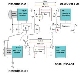
For particular reasons, our application needs to run a SER/DES configuration conformed by and arrange of two DS90UB954-Q1 serializers and two DS90UB953-Q1 (four chips).

We know DS90UB954-Q1, can handle two Serializer at the output, however, as I mentioned we need to work with a separated deserializer chips, each one connecting only one serializer, so we are wondering if is possible to interconnect both systems sharing same power supplies (PoC voltage supply, 3.3V, 1.8V) taking in account current requirements.

Please use the diagram below as reference about we are trying to identify (apologies for paint work).

Diagram

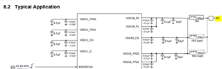
Essentially this question is coming from the fact we are trying to minimize the number of power supplies and regulators to be used (in both sides) and we would like to verify is possible with Texas Instruments, so:

  1. Is possible to interconnect Two deserializer each one with a serializer and sharing power supplies? Or
  2. We need to use independent power supplies (PoC, 3.3V, 1.8V) per subsystem Deserializer/Serializer?

Thanks for your support and waiting for your advice.

Best regards.

  • Hello Carlos,

    The TI network blocks access to file sharing sites, such as Google Drive, so I am unable to access your diagram. If you'd like, you can post a PDF or other attachment type in the forum instead.

    But anyway, yes, it is possible for separate 954 chips to be connected to the same power supply rails. You just need to make sure that each of the power supply pins on the 954 devices have their own separate set of decoupling capacitors, Ferrite Beads, etc... as defined in Typical Application section in the 954 datasheet. Depending on the noise in your system, more decoupling capacitors may be added to ensure 1.8V(+/-5%) is always supplied to the appropriate power rails.

    For example, the 1.8V voltage rail can be connected to the Ferrite Bead on the first 954 chip and the Ferrite Bead on the second 954 chip. You do not need to create 2 separate 1.8V voltage rails for each 954 device. One thing to keep in mind in your intended design is the increased current draw from the 1.8V rail.

    Please make sure to review the DC Electrical Characteristics table in the 954 datasheet in order to make sure the regulator or buck converter used is able to provide the required current to each device's power supply pin.

    Same advice for the PoC voltage. A single power supply rail can supply the PoC voltage to two 954 chips, just make sure there is a separate set of decoupling capacitors and a separate PoC network used for each device. Also make sure noise requirements can be met and that current through the PoC network does not exceed the rated limit defined in the datasheet, if you are using our recommended PoC network.

    Best,

    Justin Phan

  • Dear Justin Phan.

    Thanks for your answer, please find attached a better clarification with diagrams and notes based in your previous answer.

    COnfiguration is currently:

    1. Sharing Regulators on the Deserializer side (could be required additional decoupling caps)-> side A
    2. Single power supply rail for PoC Voltage (12V), but each device with separated decoupling capacitors and networks, even they are sharing same 12V (X &Y)
    3. Sharing Regulators on the Serializer side (could be required additional decoupling caps)-> side B
    4. Diagram below

    Could you please confirm is possible to use in our application.

    Big thanks for your support and waiting feedback.

  • Hello Carlos,

    1. Yes, you can use a single voltage regulator to provide a voltage rail that will power both 954 devices. You just need to make sure that the two 954 devices do not share decoupling capacitors and Ferrite Beads. Make sure each device has a separate set of decoupling capacitors and Ferrite Beads, as defined in the datasheet. Also make sure the regulator can support the current draw from two 954 devices. Some simulation or physical measurements may be required, in order to make sure voltage ripple does not exceed +/-5% of the target 1.8V or 1.1V required at each voltage rail pin.
    2. Yes, you can use a single 12V voltage rail to supply the PoC over the two different cable links. You just need to make sure that a separate set of PoC network circuits are used on each device. Don't share components. Also keep in mind the current limits. The recommended 4G PoC network in the datasheets state that less than 150mA current draw through the PoC network, in order to maintain the impedance characteristics at the channel's operating frequency. 
    3. If the serializers are on the same board, then you can also use a single regulator and have the 953s share the same voltage rail. Just make sure the above points are followed as well, regarding separate components for each device and current limits.

    Best,

    Justin Phan