This thread has been locked.

If you have a related question, please click the "Ask a related question" button in the top right corner. The newly created question will be automatically linked to this question.

SN65LVDM050-Q1: tPLH, TPHL, tsk(p) TI production measurements

Part Number: SN65LVDM050-Q1

Hi,

We're doing some characterization of PN SN65LVDM050QDQ1 and have noticed some slight discrepancies that I was hopeful TI could enlighten us on based off your own internal measurements.

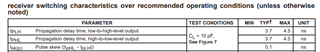
Specifically, on the receiver side, tPHL, tPLH, and the corresponding pulse skew - see results below.

tPHL
(avg)
tPLH
(avg)

tsk(p)

(pulse skew)

(avg)

+25C 3.49 0.972 2.518
-40C 3.24 0.81 2.43
+125C 4.21 1.56 2.65

Question is are these results representative of what TI has characterized internally?

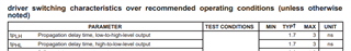
The low-to-high and high-to-low transitions are well within specification; However, the datasheet suggests those two limits should be within .1ns of each other, so wondering if there's either a discrepancy in the datasheet limits, or in our test methodology.

Thanks,

Tim

  • Hi Tim,

    Can you share you test setup? Are you following figure 5 test setup and figure 2 measurement method?

  • Hi Malik,

    I'll have to confirm exact test conditions later, but it is in my understanding we're testing to Figure 7 (SGLS128A - Timing test circuit and waveforms).

    There's some pre-provided warning the testing equipment may induce a larger load capacitance than specified on the datasheet, so we're lenient towards small discrepancies in measurements.

    However, regardless of exact test conditions, would like to know generically if tsk(p) limits should be within 0.1 ns, or we're chasing a non-issue. In my experience, typical values can be fairly unreliable sometimes, which is generally fine as a reference point.

    Thanks,

    Tim

  • Hi Tim, 

    I believe this is a non-issue, tsk(p) limits are not limited to be 0.1ns within each other. 

  • Hi Malik,

    I appreciate the feedback.

    Although, I would agree we don't suspect it will be a major issue, I'd still like to confirm empirically with TI's internal results that this is expected behavior.

    A 2-3ns pulse skew seems like it could definitely become a problem at higher bit rates, so would like to confirm if we should be accounting for this offset in the future.

    Thanks,

    Tim

  • Hi Tim,

    I agree the tPHL numbers you have are higher than I would expect. I would like to see your setup to see if there is anything going on here. 

  • Hi Malik,

    Attaching a snippet. Not much to look at.

    Device is put into a socket, and the I/O's are mapped to channels for the tester.

    The vendor provides the caveat the tester environment adds an unintended ~50pF of stray capacitance, which would serve as the CL, but would think any skew/offset that would cause from the CL=10pF test condition would be represented in both tPHL & tPLH measurements.

    Thanks,

    Tim

  • Hi Tim,

    I agree here I would expect that any effect from increased CL in both measurements. Do you see these numbers across multiple parts? An waveform you can share? Can you try adding a weak pull down or get CL lower on Y/Z pins to see if tpHL measurement is effected? 

  • These measurements are just outputted by an automatic tester, so no waveforms. We have a larger planned sample size, but presently only characterizing 3 samples to develop test limits. Unfortunately, unable to experiment with the test setup. Especially given the rest of the device seems fine, and don't want to get too burdened chasing a typical parameter.

    Why my preference is just getting indication from TI if our results are within family, or it's not, and we can just notate our results are skewed. For our purposes of evaluating pre/post life measurements; I think that's OK.

    I do think it's interesting the tPHL measurement is around the 3.7ns typical limit set on the TI datasheet, so the device being much faster on the tPLH side being the issue is perplexing.

    This is the raw data for SNs R001-R003:

    Parameter Temp Unit R0001 R0002 R0003
    tPLH_receiver +25C ns 0.8 0.9 1
    tPLH_receiver +25C ns 0.8 0.9 0.9
    tPLH_receiver +25C ns 0.8 0.8 0.9
    tPLH_receiver +25C ns 0.8 0.9 0.9
    tPLH_receiver +25C ns 1.1 1.4 1.1
    tPLH_receiver +25C ns 1.1 1.3 1.1
    tPHL_receiver +25C ns 3.4 3.5 3.6
    tPHL_receiver +25C ns 3.2 3.5 3.4
    tPHL_receiver +25C ns 3.3 3.5 3.6
    tPHL_receiver +25C ns 3.2 3.5 3.4
    tPHL_receiver +25C ns 3.6 3.7 3.8
    tPHL_receiver +25C ns 3.3 3.9 3.5
  • Hi Tim,

    Could you elaborate on the differences between each row? Are these just instances of teh same test? R0001-0003 are the three devices you mentioned correct? 

  • Sure. Each row represents one measurement in the test sequencing. I don't have it delineated by which receiver, and how many times each one was tested, but generally for the purposes of this conversation can just assume it's either/or.

    R0001, R0002, & R0003 columns are the SNs of each device.

  • I see, I think what you are seeing here is expected for the receiver and the other half of the data is for the driver.

  • Hi Malik,

    Unfortunately, I don't believe that is the case. In-application, we're only using the receiver portion, which is why my focus on on resolving the perceived discrepancy. However, the driver portion is being measured and notated separately also (pasted below).

    I do think that may be some assurance the test setup is fairly reasonable. I'm seeing averages of tPLH=1.32ns, tPHL=1.21ns resulting in a 0.11ns net average skew, which all seems reasonably within datasheet limits.

    Really, the only "problem" seems to be is tPLH on the receiver being much faster than typical. I've requested some additional information on the timing measurement to see if possibly trigger conditions or whatever are incorrect.

    Parameter Temp Unit R0001 R0002 R0003
    tPLH_DRIVER +25C ns 1.5 1.6 1.6
    tPLH_DRIVER +25C ns 1.6 1.6 1.6
    tPLH_DRIVER +25C ns 0.8 0.9 0.9
    tPLH_DRIVER +25C ns 1.2 1.2 1.3
    tPHL_DRIVER +25C ns 0.9 1.5 1.6
    tPHL_DRIVER +25C nS 1.6 1.6 1.6
    tPHL_DRIVER +25C ns 0.8 0.8 0.8
    tPHL_DRIVER +25C ns 1.1 1.1 1.1
  • Hi Tim,

    Understood, I would also like to know how these measurements are done in the program. Any waveforms to help explain would be helpful.

  • Hi Malik,

    Finally were able to resolve this discrepancy by identifying an error in the trigger conditions the tester was using to make measurements. 

    Just posting updated measurement below for any others interested. The iterations of tPLH/tPHL are different VID conditions. Much more content to see them reasonably closer to the 0.1ns datasheet limit.

    Parameter Unit R001 R002 R003
    tPLH_RECEIVER_0 ns 3.3 3.3 3.4
    tPLH_RECEIVER_1 ns 3.4 3.5 3.5
    tPLH_RECEIVER_2 ns 3.2 3.3 3.4
    tPLH_RECEIVER_3 ns 3.4 3.5 3.5
    tPLH_RECEIVER_4 ns 3.6 3.8 3.5
    tPLH_RECEIVER_5 ns 3.6 3.8 3.6
    tPHL_RECEIVER_0 ns 3.4 3.5 3.6
    tPHL_RECEIVER_1 ns 3.4 3.6 3.5
    tPHL_RECEIVER_2 ns 3.3 3.5 3.6
    tPHL_RECEIVER_3 ns 3.4 3.6 3.6
    tPHL_RECEIVER_4 ns 3.6 3.7 3.8
    tPHL_RECEIVER_5 ns 3.4 4 3.6

    Crudely overlapping both waveforms to show they're very close within one another.

    Anyways, appreciate the assistance & help.

    Thanks,

    Tim