This thread has been locked.

If you have a related question, please click the "Ask a related question" button in the top right corner. The newly created question will be automatically linked to this question.

SN65HVD09: Understand Parameters Driver and Receiver

Part Number: SN65HVD09

Dears Team,

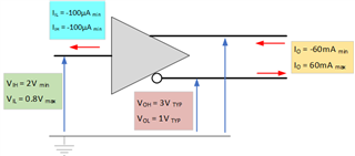
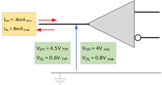
I am looking for a voltage level translator and I'm considering to use a bidirectional translation made of passive device. That type of translator needs pull-up resistors but I need some parameters in both side interconnected, in other hand I need electrical parameters from microcontroller and SN65HVD09 to size pull-up resistor value.

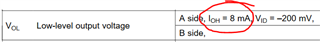
I extracted some parameters but I think that there is a mistake with condition for VOL parameter in datasheet on page 6, This should be IOL insted of IOH, Is my suggestion correct?

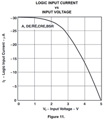
Additional, I want to know why IIL and IIH are negative.(-100uA at less) and if pictures below are right

Thank you

  • Samuel,

    An engineer has been notified of this post and will respond by the end of the work day today. Thank you for your patience.

    Regards,

    Eric Hackett 

  • Hi Samuel,

    Yes - you are correct on the typo - it should read I_OL not I_OH.

    For the direction of the current - output current is positive with respect to figure 4 in the datasheet:

    We define "positive" current as going into the single ended output and negative when it is leaving the output. 

    For the input current IIH and IIL -  this is due to the architecture of the device - essentially its a high impedance input and the majority of current is actually due to leakage which is much more temp dependent than input voltage dependent. The device has a minimum value that it won't go below. 

    For the drawings - the only thing that seems off is the output current - but it really depends on how you define it - if this is just based on the voltage output + termination resistor than its okay - but the device max current is under short circuit conditions which for this device is  +/-260mA.

    Please let me know if you have any other questions!

    Best,

    Parker Dodson

  • Hi Parker,

    Thank you for reply.

    I want to understand, Are IIH and IIL parameters for RECEIVERS o DRIVER?

    Thank you

  • Hi Samuel,

    It would be for the single ended inputs so its the control pins + A pins when A is in transmit/drive mode - as if A is in RX mode it is an output and I_OX characteristics apply.

    Best,

    Parker Dodson

  • Hi Parker,

    I think that A letter is interchangeable with D letter when talking about a driver (transmit mode), so  I agree that there is not current going into single ended input because is high impedance due to CMOS structure.

    I assume that I_I is zero in Driver test circuit, Is that right?

    Additional, Is applicable figure 11 for above test circuit?

    Best Regards,

    SAM

  • Hi Sam,

    I_I isn't zero in most cases - there is leakage current and the logic structure will have some current - it is very small though and higher temperatures are where this current will increase. In most applications it is pretty negligible. 

    So the test setup - shows how I_I would be measured for "A" but it isn't a direct test setup or comparison of figure 11. since not all logic signals are shown. However measuring this value is just sticking an ammeter between voltage source and logic input pin and have a high/low voltage (under tested conditions listed in datasheet) and recording what the ammeter records - since the input current is unaffected by what the other pins are doing (unless in case of part failure or something along those lines- in normal circumstances it is generally unaffected by the other logic/driver pins) 

    Please let me know if you have anymore questions!

    Best,

    Parker Dodson. 

  • Hi Parker,

    Can I assume I_I = 0A in calculations?

    Additional, The figure 11 is interesting since voltage is continuous from 0V to 5V like an analog voltage where I_I is function of V_I, Is voltage input continuous by power supply in that test?

    Best Regards,

    SAM

  • Hi Sam,

    I_I can be tens of microamps as indicated by figure 11 under normal circumstances - if the circuitry attached to the single ended pins will not be affected by this current (i.e. if the control signal  can sink/source mA of current - tens of microamps probably can be assumed to be essentially 0). Essentially it really is a case by case basis - in many applications it is pretty negligible however - but it is application/system dependent.

    The voltage in the test in figure 11 is measured with multiple discrete input voltage values that are then used to create an average performance curve - so its not really a "sweep" but a collection of discrete measurements - if I misunderstood what you are asking here please let me know and I will see what I can do!

    Best,

    Parker Dodson