This thread has been locked.

If you have a related question, please click the "Ask a related question" button in the top right corner. The newly created question will be automatically linked to this question.

AM26LV32E: About Fail-Safe

Part Number: AM26LV32E
Other Parts Discussed in Thread: AM26LV32,

Hi All,

I have a question about Fail-Safe.

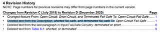
Short Circuit, and Terminated Fail-Safe has been removed from the Revision Historynioite datasheet.


AM26LV32 has the following explanation, but is AM26LV32E only supported by Open Circuit Fail-Safe?

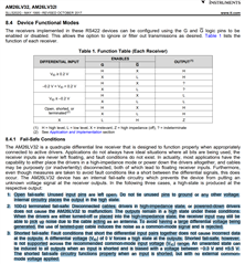
Please tell me the method of care when a terminating resistor is attached.

Best Regards,
Ishiwata

  • Hi Ishiwata,

    The "E" version of the part only supports open fail-safe while the non-E version of the part supports the three types of fail conditions listed in the picture you shared.

    More modern transceivers have more robust internal fail-safes by specifying both thresholds to be less than 0V (which therefore covers all short/open/idle conditions) - You can also add external fail-safe protection with 2 resistors for an entire system in case you are unsure about fail-safes on every part on the bus - I have a application note that goes into details on how to size the two resistors and where to place them - https://www.ti.com/lit/an/slyt324/slyt324.pdf

    Could you please elaborate what your concern is with the terminating resistor - I am not sure I follow what you are asking and I want to make sure so I am giving you the most helpful answer I can.

    Please let me know!

    Best,

    Parker

  • Hi Parker,

    I understand that The "E" version only supports open failsafe.

    Customer concerns include:
    In the non-E version, fail-safe with a terminating resistor was described,
    In the E version, I was asked that I didn't know what to do if I added a terminating resistor.
    Therefore, I asked about the case where a terminating resistor is attached. Is it necessary to connect the resistance value in the circuit diagram below from the document introduced?

    I have additional questions.
    There is a function table for the AM26LV32E datasheet.
    The range of -0.2V <VID <0.2V is indeterminate (=?), But Open is High.


    Since it is Open, I think that A = B = open and VID = A-B = open-open = 0.
    In that case, -0.2V <Open-Open <0.2V, so I think it will be indeterminate.
    Please tell me the reason why it goes High at Open.

    Thank you for your support.

    Best Regards,
    Ishiwata

  • Hi Ishiwata,

    For fail-safe resistors the terminating resistor doesn't need to be attached - as without the terminating resistor A is at VCC * R_In/(R_FS_A+R_In) and B will be at ground which cause the device to receive a logic "high" in open/idle conditions.

    If termination is used, which is recommended under RS-485 standard - the two resistors between A and B I would recommend setting them to 120 Ohms and then solving for R_FS to create a idle/open bias voltage - opposed to solving for the terminations as in the fail-safe passive application note - as this will make calculations simpler.

    That table is misleading - that's recommended operating - i.e. when valid data is being sent on the line it should conform to this standard. The device's thresholds may be lower - but how we spec'd this part is just to reflect RS-485 standard. This is not how our parts are spec'd anymore - as our tables and how we define thresholds aren't just copied from standard but reflect device operation. So the device is still safe in open conditions and shouldn't oscillate.

    Best,

    Parker Dodson

  • Hi Parker,


    Thank you for your answer.

    I understand. AM26LV32E is safe when opened and does not oscillate.

    What is the VID voltage of A-B when the terminal is open?
    Is the VID voltage made so that it will be + 0.2V or more at the time of opening?


    Thank you for your support.

    Best Regards,
    Ishiwata

  • As shown in the functional block diagram, the A/B inputs have internal weak pull-up/-down resistors, so the open VID will be large.

    If a termination resistor is connected, the inputs are not open, and VID will be smaller then 0.2 V.

  • Hi Ishiwata,

    Clemens is correct in his analysis.

    If you have any other questions please let me know!

    Best,

    Parker Dodson

  • Hi Clemens and Parker,

    Sorry for my late reply.

    I understand that it is pulled up / pulled down internally.
    I will inform the customer of this content.

    Thank you for your support.

    Best Regards,
    Ishiwata

  • Hi Ishiwata,

    You're welcome! 

    If there is any follow-up questions please let me know and I will see what I can do!

    Best,

    Parker Dodson