This thread has been locked.

If you have a related question, please click the "Ask a related question" button in the top right corner. The newly created question will be automatically linked to this question.

TIC12400-Q1: interfacing analog temperature sensors

Part Number: TIC12400-Q1
Other Parts Discussed in Thread: TIC12400

Hi Team,

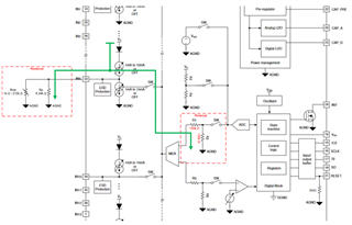
Is TIC12400-Q1 capable to bias and read analog temperature sensors (NTC) on the ADC inputs?

In theory this should be possible but there are questions:

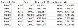
  • Wetting current is needed to bias NTC --> TIC12400-Q1 minimum wetting current setting is 1mA.
  • As NTC is in range of ~1k to ~210k, voltage on NTC could be as high as 210V.... and  this obviously violate TIC12400 input voltage range.

Is this (simple) consideration correct, or is there any other/better way to have TIC12400-Q1 bias and read NTC values? 

  • Hi Piotr,

    This is an interesting question.  I think it should be possible and after thinking about this a little bit, I believe adding a resistor in parallel with the NTC is the simplest solution. This parallel resistor will create an equivalent resistance with the NTC and mitigate the large voltage created from a high NTC resistance value. 

    I need to point out that there is also an internal resistance that needs to be placed in parallel with the external load due to the resistor divider used to scale the input voltage down to an acceptable range for the ADC.  This is specified in the datasheet as a typical 240kΩ where each resistor is roughly 120kΩ.

    Some of the wetting current will flow to ground through this internal path and not all of it will flow through the external NTC or load resistance.  Therefore there final calculations need to consider all the resistor elements in parallel.

    Because the ADC has an operating range of 0V to 6V, I did some quick calculations with an external parallel resistor (Rp) across your stated NTC resistance range (Rntc).  These two resistances create the External resistance (Rexternal), and then this is also placed in parallel with the Internal resistance (Rinternal) or 240kΩ. 

    The following table shows that with a external 6.34kΩ resistor in parallel with the NTC, the input voltage swings between 0.866V and 6.0V as a result of the NTC resistance changing between 1kΩ and 210kΩ.

    I don't know what kind of accuracy is needed or if there is more of a window of interest where they care about and are ok with letting the ADC saturate beyond that point. If so, they could adjust the resistance accordingly, but they would just need to keep the input voltage below the max specification to avoid damaging the device.  This is also just typical basic calculations that do not consider component tolerance factors.

    Regards,

    Jonathan