This thread has been locked.

If you have a related question, please click the "Ask a related question" button in the top right corner. The newly created question will be automatically linked to this question.

DP83TG720R-Q1: MDI mode conversion test using STP cable

Part Number: DP83TG720R-Q1

Hi,

We found consistent fail results in MDI mode conversion when testing our board with the DP83TG720R using STP cable.

If we look at TI's test report for DP83TG720, the MDI mode conversion test showed PASS results.

One of the main difference is that the DP83TG720 evaluation board (in the test report) was using UTP cable (MATEnet connector and cable).

We suspect that this may be related to the common mode impedance difference between STP and UTP cable assembly.

On our board and TI evaluation board (media converter board), we adopted this MDI termination design (as in the snlu289 User’s Guide DP83TG720 Media Converter Evaluation Module):
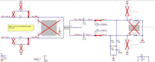
  

In this termination, the common mode impedance will be ~500ohm.

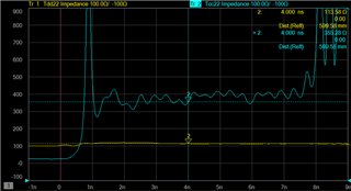
For a UTP (MATEnet) cable, we have measured that it is in the range of ~350ohm:
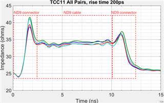
For a STP cable, due to the shielding, it is typically much lower at 30 ~40ohm range:
Hence we are wondering if DP83TG720 are meant for UTP or STP cable?

If it is to be used for STP cable, should we ignore the MDI mode conversion test in this case, as it may not be relevant.

Or there is another recommended termination design required for STP?

Please advice. Thanks!

  • Hi Teik,

    The document you mentioned, the test done was using UTP, in the past there have been others who have been successful running STP however adjustments had to be made. Given we have characterized it using UTP, we do not have suggestions for running STP. 

    What is the want/need to run STP as opposed to UTP?

    Best,

    Alon

  • Hi,

    We are using customized cable assembly that comprises of at multiple differential twisted pairs, as well as other signals.

    STP will be more suitable for our application scenarios.

    OPEN Alliance has specified both specifications for UTP and STP channel specifications for 1000BASE-T1.

    You have mentioned that for STP, adjustments had to be made.

    Would you be able to share the possible adjustments required?  

    Best regards,

    Teoh

  • Hi Teoh,

    We do not have any explicit adjustments you could make here. We will have a difficult time supporting here as we have only charactirzed the 720 for UTP. 

    When you test with your current STP line, do you get errors or dropped packets? Do you have link-up at all?

    Does the test fail?

    Best,

    Alon

  • Hi Alon,

    First of all, perhaps we can start with the MDI mode conversion failure that I have described in my initial post.

    How are we able to get pass results for MDI mode conversion based on STP cable assembly?

    Or, is the specified MDI mode conversion a necessary test for PHY transmitter in STP use case?

    Best rgds,

    Teoh

  • Hi,

    Any updates or advices on this issue?

    BR,

    Teoh

  • Hi Teik,

    Please look out for an update early next week. 

    Best,

    Alon

  • Hi Teik, 

    I have connected with team regarding this this query. 

    Are you only talking about the connector? Can you please share the name of the STP assembly you are wanting to use. 

    Best,

    Alon

  • Hi,

    As I have explained in my previous posts, we are using customized STP cable assembly with IX connectors by Amphenol.

    It is not off-the-shelf cable assembly.

    Please let me know if there are specific information you required about the cable assembly.

    BR,

    TTH

  • Hi Teik,

    Could you please provide the datasheet, and/or assembly diagram of this STP connector?

    Could you check if the connector ground is the same as board ground? If yes, can you perform the measurement with the connector ground disconnected from board ground?

    Mode conversion test results can have impact on the emissions, you are attempting to use STP cable so the EMC performance can be better then what is seen on internal testing using UTP. You should also evaluate your EMC performance to see if mode conversion needs to be improved for your case or not. 

    Best,

    Alon

  • Hi Alon,

    I am sending you a separate private message for sharing the datasheet.

    What is the purpose to disconnect the connector ground from the board?

    How does this link to the common mode impedance or the MDI mode conversion measurement?

    As I have explained in my initial post, we think that the MDI mode conversion likely is affected due to the difference in common mode impedance between STP and UTP cable assembly. If we do not change any PHY settings or MDI termination design, we may not be able to change the outcome of the MDI mode conversion. But if changes are required, what kind of changes required?

    BR,

    TH

  • Hi Teik,

    Thank you for sending that piece of information. I have reached out with your query to some senior team members. 

    Their comments are as follows:

    We don't have options to improve mode conversion results with this assembly

    We recommend using standard automotive connectors like MATENet, HMTD, etc. with specs as defined by IEEE

    I know this is not the answer you were looking for however, it is difficult for us to comment on designs that are distant from anything we define in datasheet, or tested in lab. 

    Best,

    Alon