This thread has been locked.

If you have a related question, please click the "Ask a related question" button in the top right corner. The newly created question will be automatically linked to this question.

THVD1450: Not receiving the packets after attaching in a modbus network as a slave after a short interval of time!

Part Number: THVD1450

Hi All,

I am using THVD1450 as the RS485 receiver in a modbus slave type devices. Everything is working perfectly in the lab situation. But when we installed in a specific network of 400 meters we started seeing a problem of the receiver stopped receiving the packets.

We verified the same by running an in-circuit debugger in the corresponding slave system and continuously sent packets in few seconds interval. We verified the packets in the network but couldn't see any reception by the particular slave machine using THVD1450 receiving any of those packets. 

Another observation is that when we power cycle the board then immediately the device show up in the network as the transceiver is properly receiving the packets now.(Software stack problem ruled out as we tried resetting the microcontroller keeping the power intact, still the receiver didn't receive any)

My thinking is that the transceiver is entering to some idle bus state error stage and not coming out from it even the master starts sending the packets. 

If above is correct how to take the THD1450 out from that state without a power recycle? Or any other is the root cause please share some pointers.

Thanks and Regards

-Jabir

  • The THVD1450 does not have any such state.

    Please check with an oscilloscope or logic analyzer at the R and /RE pins if the data comes out of the THVD1450.

  • Hi Jabir,

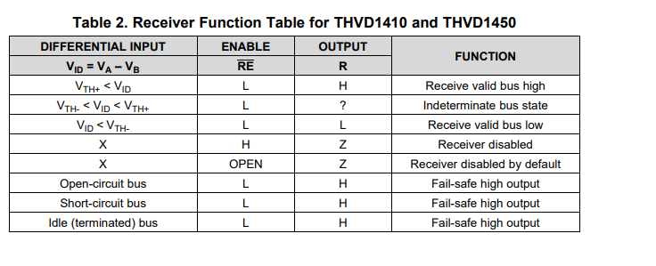
    The device, a s Clemens mentioned, doesn't really the modes that you are speaking of - have you verified the voltages according to the Rx table on the device in question:

    This is what determines the "R" pin state (received data stream). This is going to be a measure of A/B/ /RE and R at times of issue. 

    Also how many nodes are in the system (how many RS-485 transceivers on the bus) ?

    Is the system terminated? If yes - what is the termination and where are there termination resistors in the system?

    What kind of cable or transmission line was used ?

    What is the desired data rate of the application?

    Based on the answers to the above questions it can help me see if it is just an application issue (i.e. how everything is being used) or if there is something larger at play. From the initial tests that you have done it seems like the length could be a large contributing factor - but I am not sure to what degree that may be. 

    Please let me know so I can help try to get to the bottom of the issue!

    Best,

    Parker Dodson

  • Hi Clemens and Parker,

    Thanks a lot for your time in responding to my queries.

    For your Questions please find the answers below,

    This is what determines the "R" pin state (received data stream). This is going to be a measure of A/B/ /RE and R at times of issue. - R is always read high

    Also how many nodes are in the system (how many RS-485 transceivers on the bus) ? - Designed for 21 systems but testing this issue with only 3 -4 systems

    Is the system terminated? If yes - what is the termination and where are there termination resistors in the system? - Tried with and without termination. 120 Ohms. Bit error rate is not all our issue as till this issue occurs we don't have any single packet loss

    What kind of cable or transmission line was used ? - CAT 6 three core cable

    What is the desired data rate of the application? - 9600 only.

    Let me put some re emphasize on the information about the system. In lab we have not seen this issue so far. And in the field the systems are perfectly communicating till this issue occurs. The duration of proper working in field can be a 3 to 10 mins of duration randomly. Also if we power recylce the issue the device starts communicating immediately. But if keeping the power intact if we do a MCU rest the communication is still in same non receiving condition.

    Thanks and Regards

    -Jabir

  • Please check that /RE is low. How is it controlled?

    Is it possible that there is noise larger than ±18 V? Does the circuit have protection against that?

  • Hi Clemens,

    The RE is controlled by the microcontroller and it was ensured it is kept low as we were having our debugger connected to the system. 

    For your comment - Is it possible that there is noise larger than ±18 V? Does the circuit have protection against that?

    1) If this is the case other systems also would have stopped working rt. Out of four test devices each one will lose the communication in entirely different time points which are 2 to 15 mins in random duration.

    2) For the protection - We are not discussing about a damage condition here. The moment we power cycle the system it is very much healthy and responding to our master sent commands.

    I wish to take your attention towards that power cycle scenario so that we may get some clue of what is really happening.

    Thanks and Regards

    -Jabir

  • This device does not have any internal state; it should not be possible for it to lock up.

    The only explanation I have is that some voltage at the bus or power pins is out of range. Can you show oscilloscope traces of those pins in the field?

  • Hi Jabir,

    I don't think its a damage issue first off - that doesn't seem likely based on everything you have shared.

    That being said - if R is going high and is stuck that way - it could be the device responding to a "fail" condition (either open bus, shorted bus, or idle bus) and will output high (this isn't really a different state of the device - its internal thresholds count a voltage of -20mV or greater logic high preventing idle/short/open conditions from potentially oscillating) 

    If this is happening in the field my question is what is different between lab and field tests - is it length or are there more changes?

    The next step to identifying the problem is to measure the A/B bus at the receivers in question. I'd imagine what you will see is after the system runs for a few minutes the voltage there is going to drop and it may be falsely reading a logic high at all times. This test will tell you/customer and myself if its an actual receiver problem or if there is some event in the system that causes attenuation - what that may be is variable but at this moment it could be 100% system level issue and nothing to do with the transceiver itself - I can't say that with 100% certainty if that's the case but understanding the voltage levels at the A/B pins of the receiver is the next best step to isolating the issue being seen.

    Please let me know if these results can be gathered from the field because the problem seems to be field specific and I am not sure the lab is able to capture the real system adequately in this case.

    Best,

    Parker Dodson

  • Hi Parker, 

    Thanks for the detailed analysis. I think you have touched up on the point mentioned by Clemens as well viz; "This device does not have any internal state" which is mentioned in the datasheet page number 19 Section 9.3 paragraph 2. 

    I also agree that the device may be in one of these state mentioned by datasheet. This leaves us two options as below,

    1) If this state is happening due one of the reasons or due to the reason mentioned by Parker, why is not happening to another device close to the same system

     Observations to add to above point

    a. We have enabled multiple system in the bus(say 4 numbers, farthest, shortest, middle two with respect to the master). Any of these devices will stope responding in any random manner. sometimes we lose the shortest first , some times the middle and the farthest. Hope this gives light to the voltage condition about the bus.

    b. If voltage level of bus is the issue, why no two devices are stopping response at the very same instant.

    2) I am not trying to conclude that the receiver has an issue. But we are almost sure that the receiver is going to one of its fault state which is not a short circuit or open one(theoretically) except the idle condition. If we assume it is assuming idle state my main question is how to take the driver out of the idle fault condition programatically. A solution to this can be a very good work around to solve my current filed condition. Later the issue can be properly characterized for further analysis.

    Note: Lab and Filed difference is a small addition of length only. Lab we tested with 300 meters(a worst case wire guage for simulating limits), in filed it is merely more than 400 meters with CAT6 cable.

    A solution to bring the device out from a idle fault state itself will help to formulate so many further test cases to characterize the issue. So looking forwards for some hints towards that.

    Thanks and Regards

    -Jabir

  • We do not have enough information. Please show oscilloscope traces of A/B/VCC.

  • After sharing this much information its doesn't seems like don't have enough information. Given this much test cases the VCC situation of the system and all can be easily understandable.

    Jabir

  • Hi Jabir,

    I don't think its the length - 9600bps at 400m shouldn't be an issue under normal circumstances - and since the units having issues are length independent I doubt its an attenuation issue (which it shouldn't be based on operating specs)

    As mentioned earlier there isn't internal states - so the bus idle mode to the receiver is just a logic high voltage. There is nothing that will cause it switch to a low voltage unless the A/B voltage registers a low state. Understanding 1. if this is actually the problem and 2. what the signal at A/B look like for devices that are failing communication is critical for finding a solution. With the information that  I have right now I can really only assume that the design is ok (tested in lab - the slightly shorter length probably isn't having that large of an effect) so information from the field system would be important as I don't have a solution when I am not sure of the problem - I can speculate but that doesn't help as without more its really just me listing every possible outcome when scope shots will tell me more about the issue at hand and will give me enough information to dig deeper into the issue.

    Best,

    Parker Dodson