This thread has been locked.

If you have a related question, please click the "Ask a related question" button in the top right corner. The newly created question will be automatically linked to this question.

TPS25750: PD writing unexpected I2C command to REG 0A after negotiation

Part Number: TPS25750
Other Parts Discussed in Thread: BQ25792

I have the USB power delivery part (TPS25750) connected to the I2C bus of the BQ25792 battery charger.  I am setting up a test with two series batteries that I will charge at 2A up to 8.4V.  I have modified PROG pin to 8.2k so that the switcher in the BQ25792 will operate at 750kHz (2.2uH inductor) and I correctly see 8.4V as the target voltage when I boot if PD negotiation has not occurred and the TPS25750 has not written to the BQ registers.  This is REG01 having a hex value of 0348 (setting of "840", or 8400mV, or 8.4V).

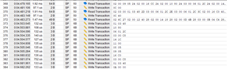
However, when PD negotiation runs, there is an extra command that is sent to REG 0A of the BQ charger. This register is not involved at all with the binary file I've created from the GUI, at least not that I can see. Additionally, I see the PD part correctly write 0348 to register 01 earlier in the sequence of writes the TPS25750 autonomously does after PD negotiation to 9V.  From what we can tell, this write to 0x0A has the side effect of changing the value of REG 01 to 01A4 (420, or 4200mV, or 4.2V) and we aren't sure why 0x0A is written at all.

Is it expected that 0x0A should be written as "00 00" at the end of the PD sequence?  Beyond this being an unexpected write, the fact that two bytes are written is also weird because REG 0A is only one byte in length. If we manually write REG 0x0A to 0x63 after PD runs, then REG 01 correctly flips back to the value of 0348 (8.4V), which is what we want to charge our 2s battery config.

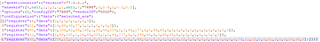
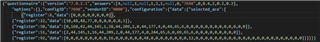
I am including the binary file we are using with our EEPROM and a screen cap of the I2C events that happen at boot time.

  • In this screen cap of the I2C writes that occur at boot time:

    1) The black bracketed section is the end of the TPS25750 reads from the EEPROM

    2) The red bracketed section are the writes from the TPS25750 to the BQ25792, based on the reads from the EEPROM and the negotiation with the USB PD host adapter.

    3) The blue bracketed section are the manual writes our software does to the BQ25792 after PD has completed.  To fixe the problem we are seeing (1s config instead of 2s config), we have to add another write of 0x63h to REG 0x0A, which is not shown in this capture.

  • I'm finding it impossible to attach a binary file or a JSON file to this page so I can't include my binary file that is on the EEPROM, for now. Let me know if you have any suggestions. I am trying "Insert" -> "Image/video/file" and it doesn't seem to take the files I provide.

  • Hi,

    Our team member will get back to you as soon as possible.

    I believe .bin and.json file can be uploaded by dragging it directly to the text box, please let us know if this method does not work and we can find other ways to upload the file.

    Regards.

  • This is what it looks like when I drag and drop with the binary file right before I release the mouse button to drop it. I see a very momentary message about uploading the file right after that (can't capture it bc it is so brief), but then I don't see any attachment added.

  • For now, here is an image of the JSON file options in a text editor. I manually made new lines every so often so that this would be more readable as an image, but it appears as a single continuous line of text when I first open it.

  • Sam,

    We have released a new version of the TPS25750 GUI that has a fix for the issue that you are seeing.

    Try using this link:  https://dev.ti.com/gallery/view/USBPD/TPS25750_Application_Customization_Tool/ver/7.0.3/

    If you log into the GUI again and read the JSON file that you have, it will load the configuration and build the binary based on your current configuration.

  • Thanks, Chuck. My software engineer is OOTO today and Friday, but I have generated a new binary file with the latest version of GUI you provided and I will have him help me attempt it on Monday. Will keep you posted.

  • Thanks for the update.  I will leave this thread open for a few more days to await your feedback.

  • Hi Chuck,

    We tried the binary generated from the new GUI today and we are seeing problems. The same binary file/settings generated from GUI version 7.0.2.1 works (aside the extra write to 0x0A), but GUI version 7.0.3 fails.  Here are some I2C captures.

    GUI version 7.0.3 at the end of the binary writes from EEPROM plus the commands the PD part tries to write to the BQ part autonomously. Note that there is a time out after this last command in this capture and then nothing else is sent by the PD part. Passthrough commands are not working because the PD part has not correctly entered APP mode.

    GUI version 7.0.2.1 at the end of the binary writes from EEPROM plus the commands the PD part tries to write to the BQ part autonomously. All the writes work and the part enters APP mode:

  • Sam,

    Can you send me the latest JSON that you are working with?  I have not seen or heard of failure to enter app mode with the latest GUI.

  • Here is the JSON I exported from GUI version 7.0.3.  I did just notice it still has the version 7.0.2.1 tag in the JSON file itself, which is a bit odd to me. I created this JSON from that GUI version originally, but imported it to version 7.0.3 and then re-exported from 7.0.3 so I'm not sure if there is anything I need to do differently.

  • Sam,

    Thanks.  I will be able to look at this later this week.

    Chuck